
Wireless communication system, wireless base station, and wireless communication method

a wireless communication and wireless technology, applied in the field of wireless communication systems, wireless base stations, wireless communication methods, can solve the problems of wasting the radio capacity of the upstream line, unable to efficiently use the power of the signal received by another wireless base station, and difficult to simplify the network configuration. , to achieve the effect of increasing the upstream radio capacity, simplifying the network configuration, and reducing the transmission power

Inactive Publication Date: 2009-11-12
NEC CORP
View PDF3 Cites 0 Cited by
  • Summary
  • Abstract
  • Description
  • Claims
  • Application Information

AI Technical Summary

Benefits of technology

The present invention provides a wireless communication system with a simplified network configuration. The system includes multiple adjacent wireless base stations that communicate with a terminal. The system includes an antenna for receiving a signal from the terminal, reception amplification means for amplifying the signal, distribution means for distributing the amplified signal to an adjacent wireless base station, and demodulation means for demodulating combined signals. The system can output either the signal demodulated by the wireless base station or the adjacent wireless base station based on the received power of the signal. The wireless base station control device requires no selection or combination of signals from multiple wireless base stations, reducing complexity. The system also reduces the transmission power for controlling the terminal and increases the upstream radio capacity. Overall, the invention simplifies network configurations and improves efficiency.

Problems solved by technology

However, in the above-mentioned wireless communication system, a wireless base station control device requires a procedure for performing hand over processing, and it is difficult to simplify a network configuration.
In addition, since a terminal performs power control depending on the transmission power control signal for setting the lowest possible transmission power, upstream data is transmitted at a transmission level at which a sufficient reception level can be acquired with any one wireless base station, which results in a failure to efficiently use the power of the signal received by another wireless base station during hand over processing, and a wasting of the radio capacity of the upstream line.
In addition, in the method described in the patent document, a peripheral base station other than the key base station corresponding to the wireless base station control device cannot select or combine the upstream data transmitted from a terminal.

Method used


Image

  • Wireless communication system, wireless base station, and wireless communication method
  • Wireless communication system, wireless base station, and wireless communication method
  • Wireless communication system, wireless base station, and wireless communication method

Examples


Embodiment Construction

[0043]Described below is the exemplary embodiment of the present invention with reference to the attached drawings.

[0044]FIG. 3 shows an example of three wireless base stations according to the present invention, and the area covered by each of the wireless base stations.

[0045]An example of the present configuration includes adjacent wireless base stations 110, 120, and 130 as shown in FIG. 3, and the area covered by wireless base station 110 is divided into three cells 119-1 to 119-3. The area covered by wireless base station 120 is also divided into three cells 129-1 to 129-3. The area covered by wireless base station 130 is divided into three cells 139-1 to 139-3.

[0046]FIG. 4 shows an exemplary embodiment of the wireless communication system according to the present invention.

[0047]The present embodiment includes wireless base stations 110,120, and 130 as shown in FIG. 4. In addition, wireless base station 110 is provided with antennas 111-1 to 111-3, reception amplification sect...


PUM


Abstract

A signal transmitted from a terminal is received by plural adjacent wireless base stations (110, 120), the signal received by antenna (111-3) of wireless base station (110) and antenna (121-1) of wireless base station (120) is amplified by reception amplification section (112-3, 122-1), the signal amplified by reception amplification section (122-1) is distributed by distribution section (123-1) to wireless base station (110), the signal distributed by distribution section (123-1) is combined with the signal amplified by reception amplification section (112-3) by demodulation section (114), and then demodulated.

Description

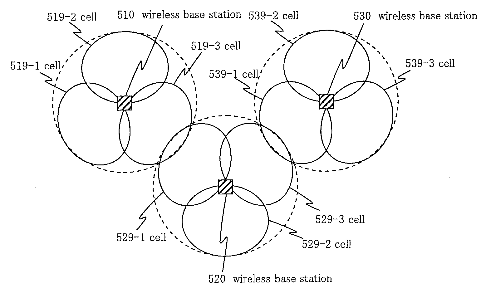
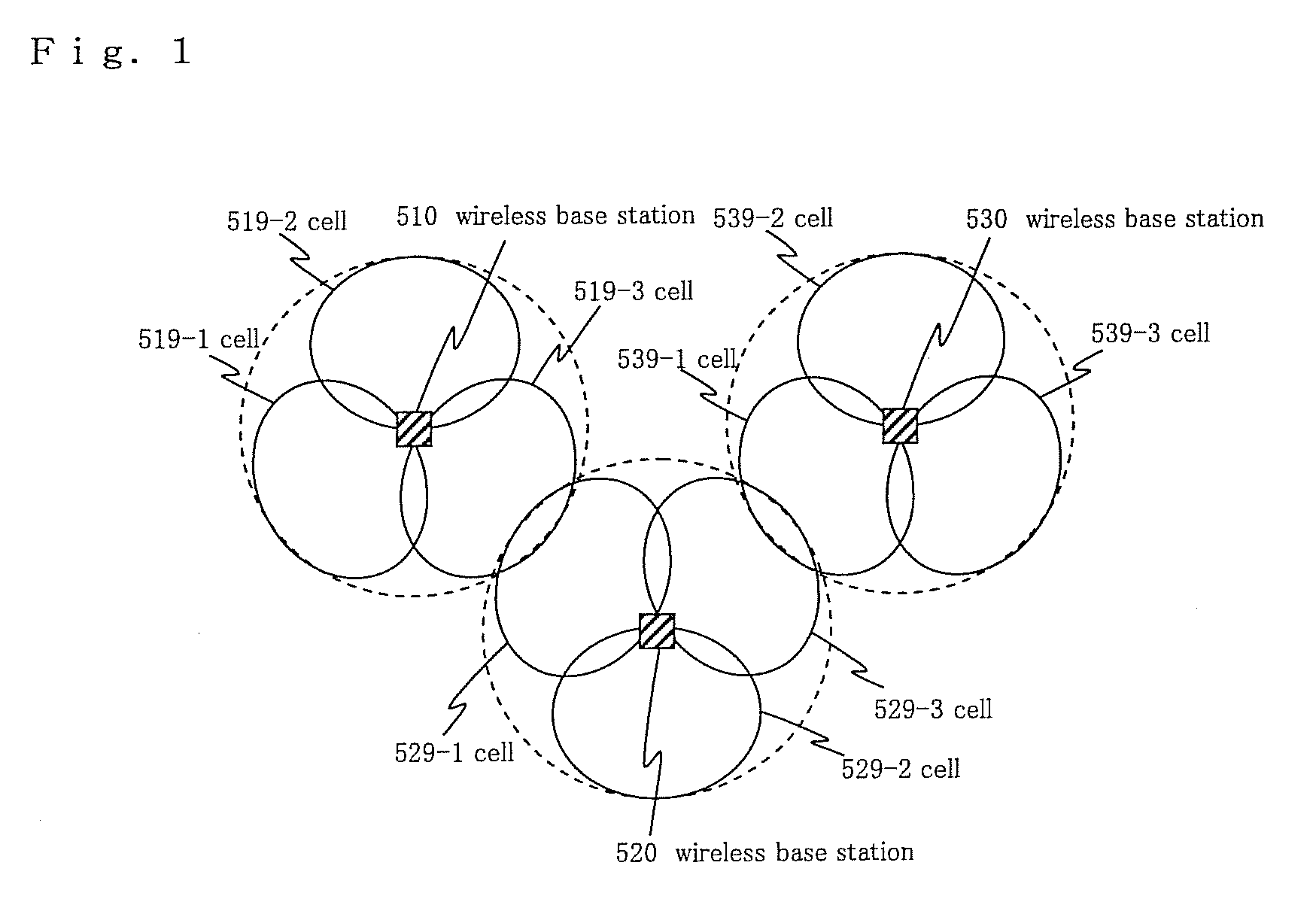
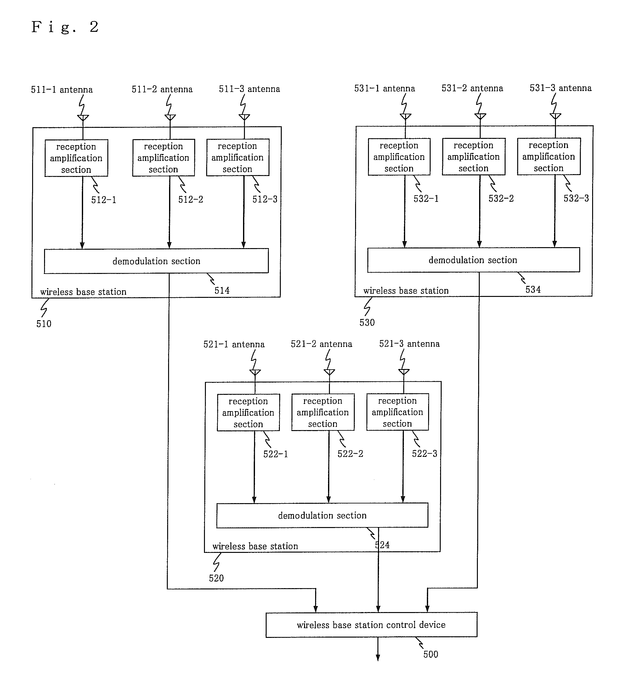
TECHNICAL FIELD[0001]The present invention relates to a wireless communication system, a wireless base station, and a wireless communication method, and more specifically to a wireless communication system, a wireless base station, and a wireless communication method for performing hand over processing.BACKGROUND ART[0002]Generally, in the wireless communication system, the hand over processing performed by mobile terminals requires the procedure in a wireless base station control device for controlling a plurality of wireless base stations.[0003]FIG. 1 shows three wireless base stations arranged as an example of a configuration of an area covered by each wireless base station.[0004]The example of the configuration includes wireless base stations 510, 520, and 530 adjacently mounted as shown in FIG. 1, and the area covered by wireless base station 510 is divided into three cells 519-1 to 519-3, and the area covered by wireless base station 520 is divided into three cells 529-1 to 52...

Claims


Application Information

Patent Timeline
Patent Type & Authority Applications(United States)
IPC IPC(8): H04W36/00H04W52/14H04W52/24H04W52/40H04W88/08
CPCH04W36/18H04W52/146H04W88/08H04W52/248H04W52/40H04W52/245
Inventor IWASAKI, MOTOYA
Owner NEC CORP
Learn More