
Intelligent implement having metal encased passive radio frequency transponder and examples of use

a radio frequency transponder and intelligent technology, applied in the field of surgical implements and computer assisted surgical instruments, can solve the problems of metal encased transponders, metal encased transponders, plastic encased materials can eventually be broken down in a typical sterilization environment, etc., and achieve uniform wall thickness

Active Publication Date: 2009-11-19
VIANT AS&O HLDG LLC
View PDF12 Cites 14 Cited by
  • Summary
  • Abstract
  • Description
  • Claims
  • Application Information

AI Technical Summary

Benefits of technology

"The patent describes a metal-encased passive radio-frequency transponder assembly. The assembly includes a metal housing with an opening that can be closed with a metal cover to create a solid metal encasement. The interior space of the encasement is defined by the interior walls of the housing and the cover. The thickness of the metal encasement is very thin, less than 0.5 mm, between the interior wall surface where the antenna assembly is located and the external surface of the housing. The assembly also includes a passive radio-frequency transponder device with an iron core antenna assembly. The antenna assembly is placed next to the interior wall surface and is designed to maximize the coupling of a radio-frequency signal to the antenna. The technical effect of this design is a highly efficient and reliable transponder that can withstand extreme environmental conditions."

Problems solved by technology

However, such references do not describe a functioning means of encasing the transponder in metal.
Sterilization of implements subjects the instrument to a harsh environment which can damage an RFID transponder.
Further, there is a perceived fear that any plastic encasing material can eventually be broken down in a typical sterilization environment such as in an auto-clave.
Currently, precision is increased at considerable cost, as more precise machining methods are required to attain the higher and higher precision implements.

Method used


Image

  • Intelligent implement having metal encased passive radio frequency transponder and examples of use
  • Intelligent implement having metal encased passive radio frequency transponder and examples of use
  • Intelligent implement having metal encased passive radio frequency transponder and examples of use

Examples


example 1

Reading Passive RF Transponders Through a Fully Sealed Metal Encasement

Objectives

[0037]Feasibility Determination: is it possible to read a passive RF transponder device through solid metal.[0038]Elucidate a set of electro-physical parametric limits for the capability to read a passive RF transponder device through solid metal.[0039]Transponder design features[0040]Thickness of the metal encasement[0041]Read distance and orientation of the read unit to the antenna of the transponder.

Materials

[0042]601201 Sokymat GLASS TAG UNIQUE 2.12×12.0 Read Only 64 bit (FIG. 6A)[0043]601203 Sokymat GLASS TAG UNIQUE 3.15×13.3 Read Only 64 bit (FIG. 6B)[0044]Test Plate C6335 (FIG. 6C)[0045]Reader: RFID tag reader with Ferrite Antenna (FIG. 6D)

Methods

[0046]A test plate C6335 was manufactured from 17-4 Stainless Steel, which is an alloy common in orthopaedic instrumentation. Both 12 mm (ITM# 601201) and 13 mm (ITM# 601203) read only Glass Unique tags were imbedded into holes drilled in the plate at va...


PUM


Abstract

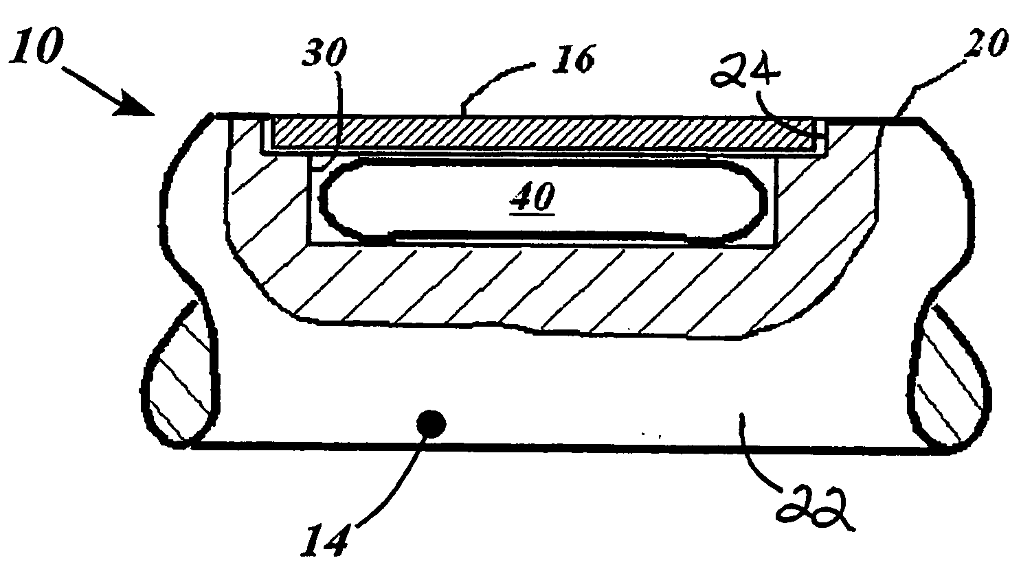
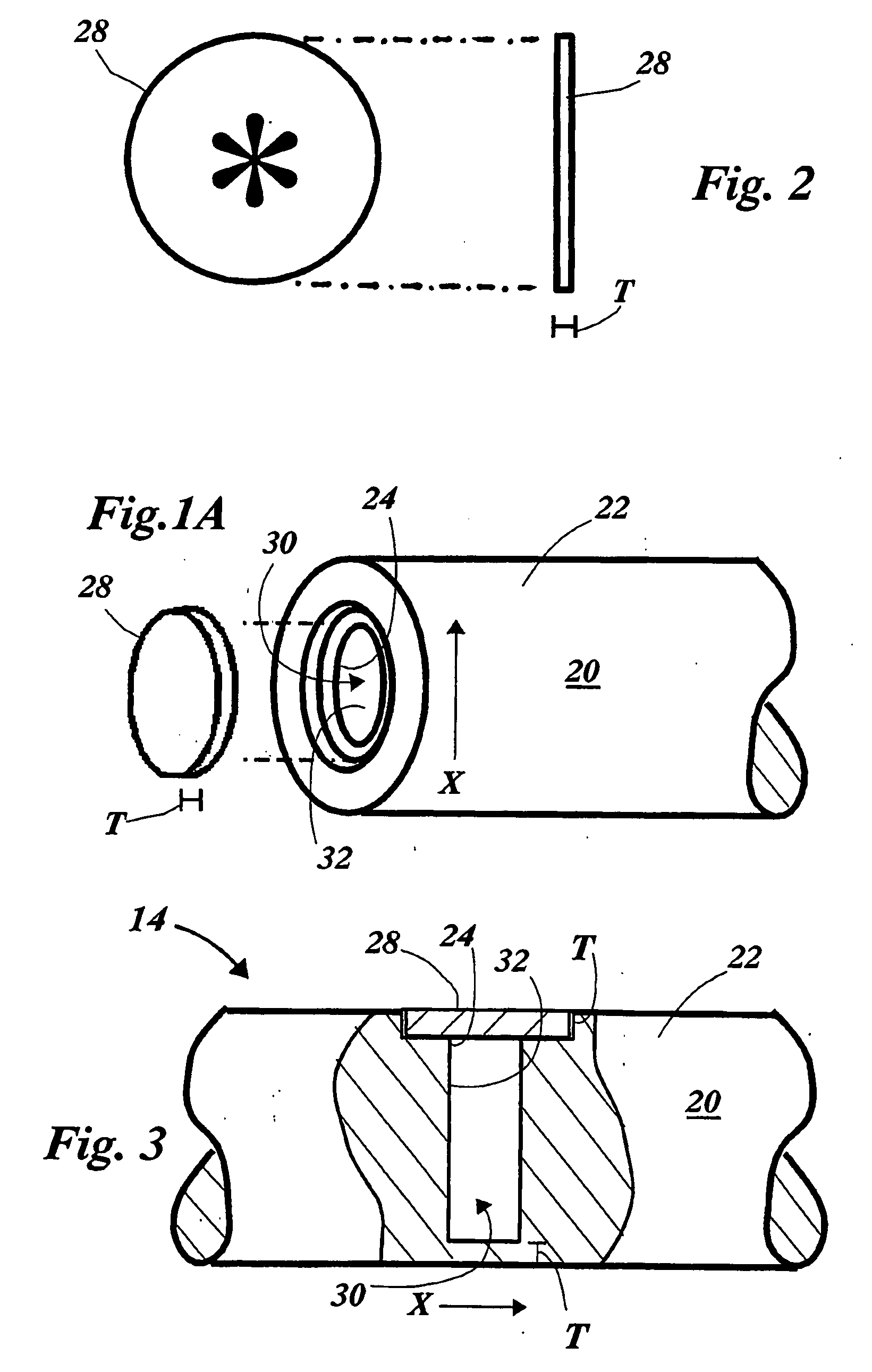
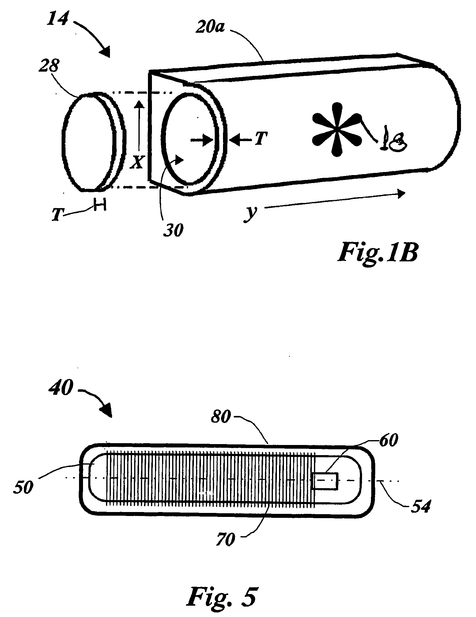
A metal-encased passive radio-frequency transponder assembly includes a metal housing having an external surface and an opening accessing an interior space, the opening closeable with a metal cover to provide a solid metal encasement The interior space of the encasement is defined by the interior walls of the housing and cover. The solid metal encasement has a substantially uniform wall thickness between the interior wall surface adjacent which an antenna assembly is disposed and the opposing external surface of less than about 0.5 mm. A passive radio-frequency transponder device is received within the interior space of the housing. The passive transponder device has an iron core antenna assembly. The antenna assembly is disposed adjacent the interior wall surface of the interior space and oriented to maximally couple a radio-frequency signal present at the interior wall surface to an antenna of the antenna assembly.

Description

CROSS REFERENCE TO RELATED APPLICATIONS[0001]This PCT application claims priority to U.S. Provisional Applications Ser. No. 60 / 639,235 entitled METAL ENCASED PASSIVE RADIO FREQUENCY TRANSPONDER AND MATERIAL TRACKING SYSTEM, filed Dec. 22, 2004 and Ser. No. 60 / 669,953, entitled INTELLIGENT IMPLEMENT HAVING READABLE ELEMENT PROVIDING PRECISE SIZE INFORMATION TO IMPROVE SURGICAL ACCURACY, filed Apr. 8, 2005, the contents of which are incorporated herein by reference thereto.BACKGROUND OF THE INVENTION[0002]This invention relates to operative, computer assisted surgical implements and related systems, and more particularly, to implements and corresponding systems which include radio frequency identification transponders encased in intelligent instruments used at the operative site.[0003]The need for such encased RFID transponders is known from German Patent application DE10239710A1. However, such references do not describe a functioning means of encasing the transponder in metal.[0004]F...

Claims


Application Information

Patent Timeline
Patent Type & Authority Applications(United States)
IPC IPC(8): G06Q90/00G06K19/06A61B19/00
CPCA61B19/44A61B19/5244A61B2017/00725A61B2019/547A61B2019/5251A61B2019/5255A61B2019/448A61B2034/2055A61B34/20A61B90/90A61B90/98A61B2034/2051A61B2090/397
Inventor WHITE, PATRICK M.BERDOZ, PATRICKFEHLBAUM, PHIIPPE
Owner VIANT AS&O HLDG LLC
Learn More