High efficiency core antenna and construction method

a technology of high efficiency and core antenna, which is applied in the direction of ferromagnetic core loop antenna, inductance with magnetic core, inductance with ferromagnetic core, etc., can solve the problem of reducing the magnetic field in the magnetic core at the end portions of the core, reducing the utilization of the core, and lowering the magnetic field about the core of the antenna

Active Publication Date: 2007-04-24
SENSORMATIC ELECTRONICS CORP
View PDF6 Cites 20 Cited by
  • Summary
  • Abstract
  • Description
  • Claims
  • Application Information

AI Technical Summary

Problems solved by technology

However, the intensity of the magnetic field in the magnetic core tends to decrease at the end portions of the core due to self-demagnetization of the core.
This results in a decrease in the utilization of the core, and, consequently, a lower magnetic field about the core of the antenna.
In many situations, however, it becomes impractical to reduce the number of turns due to physical limitations in achieving good coupling to large core structures with a low number of turns.
The impedance transforming device is, however, an additional and expensive component.
When the impedance transforming device is a transformer, additional problems may occur such as the introduction of additional resonant tank circuits with magnetizing inductance of the transformer in the equivalent circuit and the generation of high voltage spikes in the transformer secondary.
However for longer core antenna lengths, it is difficult to manufacture cores in a single piece.
Such air gaps between the contacting surfaces of the individual core components can be caused by mechanical stresses that cause the core antenna assembly to bend from its original straight position.
Since the core components are typically brittle materials, e.g., ceramic magnetic materials, such stress forces can result in damage, e.g., chipping, to the core material at the comers of the end to end joints causing air gaps.

Method used


Image

  • High efficiency core antenna and construction method
  • High efficiency core antenna and construction method
  • High efficiency core antenna and construction method

Examples


Embodiment Construction

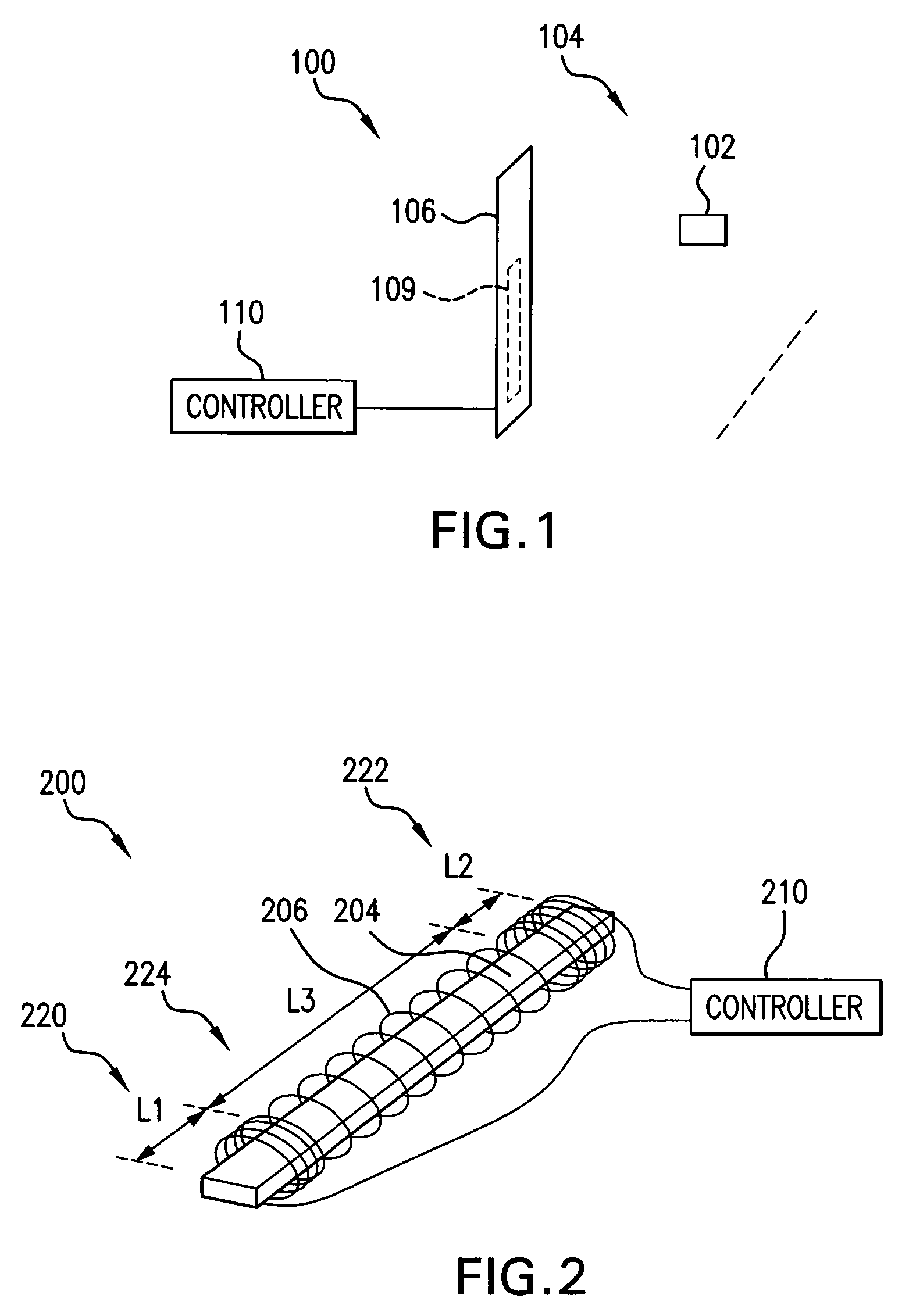
[0033]For simplicity and ease of explanation, the present invention will be described herein in connection with various exemplary embodiments thereof associated with EAS systems. A core antenna consistent with the present invention may, however, be used in connection with an RFID or other system. It is to be understood, therefore, that the embodiments described herein are presented by way of illustration, not of limitation.

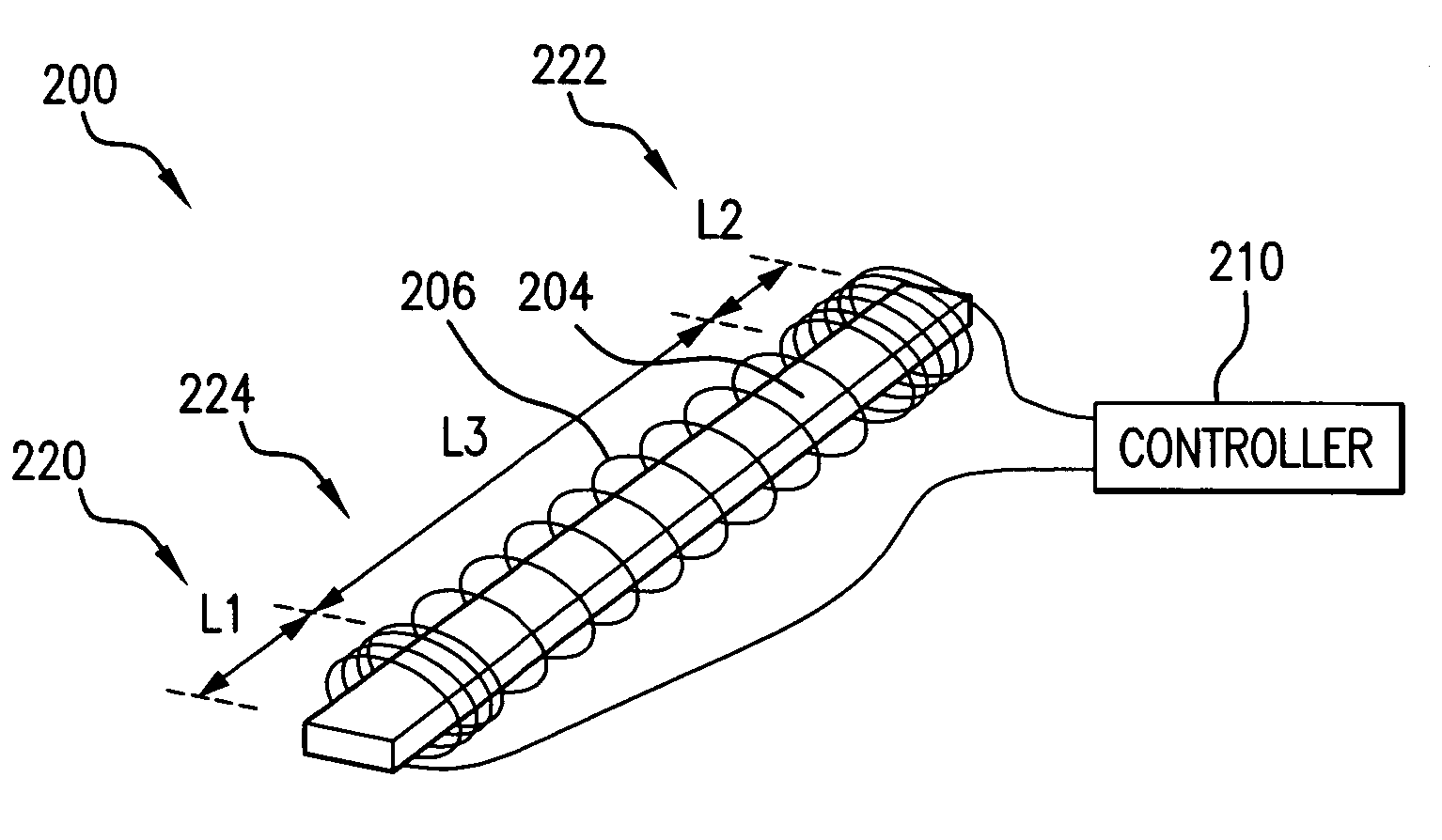
[0034]Turning to FIG. 1, there is illustrated an EAS system 100 including a core antenna 109 consistent with the invention. The EAS system 100 generally includes a controller 110 and a pedestal 106 for housing the core antenna 109. The controller 110 is shown separate from the pedestal 106 for clarity but may be included in the pedestal housing. In the exemplary embodiment of FIG. 1, the antenna 109 is configured as a transceiver and the associated controller 110 includes proper control and switching to switch from transmitting to receiving functions at predetermi...


PUM

PropertyMeasurementUnit
lengthaaaaaaaaaa
lengthaaaaaaaaaa
lengthaaaaaaaaaa

Abstract

A magnetic core antenna system including a magnetic core and a winding network. The winding network may be configured with a non-uniform ampere-turn distribution to achieve a desired flux density in the core. The network may include a plurality of windings configured to provide a winding impedance facilitating optimal transmitter power delivery to the windings. A magnetic core may be constructed from multiple components having longitudinal contact surfaces and joined by a transverse clamping force. An air gap may be provided between the components to allow relative movement therebetween.

Description

CROSS-REFERENCE TO RELATED APPLICATIONS[0001]This application claims the benefit of U.S. Provisional Application Ser. No. 60 / 478,943, filed Jun. 16, 2003, the teachings of which applications are incorporated herein by reference.FIELD OF THE INVENTION[0002]The present invention relates to magnetic core antennas, and, in particular, to a high efficiency magnetic core antenna for use in a variety of systems such as an electronic article surveillance (EAS) or a radio frequency identification (RFID) system.BACKGROUND[0003]EAS and RFID systems are typically utilized to protect and track assets. In an EAS system, an interrogation zone may be established at the perimeter, e.g. at an exit area, of a protected area such as a retail store. The interrogation zone is established by an antenna or antennas positioned adjacent to the interrogation zone. The antenna(s) establish an electromagnetic field of sufficient strength and uniformity within the interrogation zone. EAS markers are attached to ...

Claims


Application Information

Patent Timeline
Patent Type & Authority Patents(United States)
IPC IPC(8): H01Q7/08G08B13/24H01F17/04H01Q1/00H01Q1/22H01Q7/06H01Q21/00
CPCH01Q1/22H01Q1/2216H01Q7/06H01Q7/08H01Q21/00H01F17/045
Inventor HALL, STEWART E.BALCH, BRENT F.COPELAND, RICHARD L.FARRELL, WILLIAM
Owner SENSORMATIC ELECTRONICS CORP
Why Eureka
Try Eureka