Hovering aerial vehicle with removable rotor arm assemblies

a technology of rotating arms and aerial vehicles, applied in the field of aerial vehicles, can solve the problems of expensive replacement of one and damage to the vehicl

Active Publication Date: 2009-11-19
AERYON LABS
View PDF5 Cites 247 Cited by
  • Summary
  • Abstract
  • Description
  • Claims
  • Application Information

AI Technical Summary

Problems solved by technology

In use, these aerial vehicles are typically controlled by a remote control, however, as will be understood, there may be hidden obstacles which can damage the vehicle while in flight.
As it is quite expensive to replace one of these vehicles, it is necessary to provide protection to the vehicle.

Method used


Image

  • Hovering aerial vehicle with removable rotor arm assemblies
  • Hovering aerial vehicle with removable rotor arm assemblies
  • Hovering aerial vehicle with removable rotor arm assemblies

Examples


Embodiment Construction

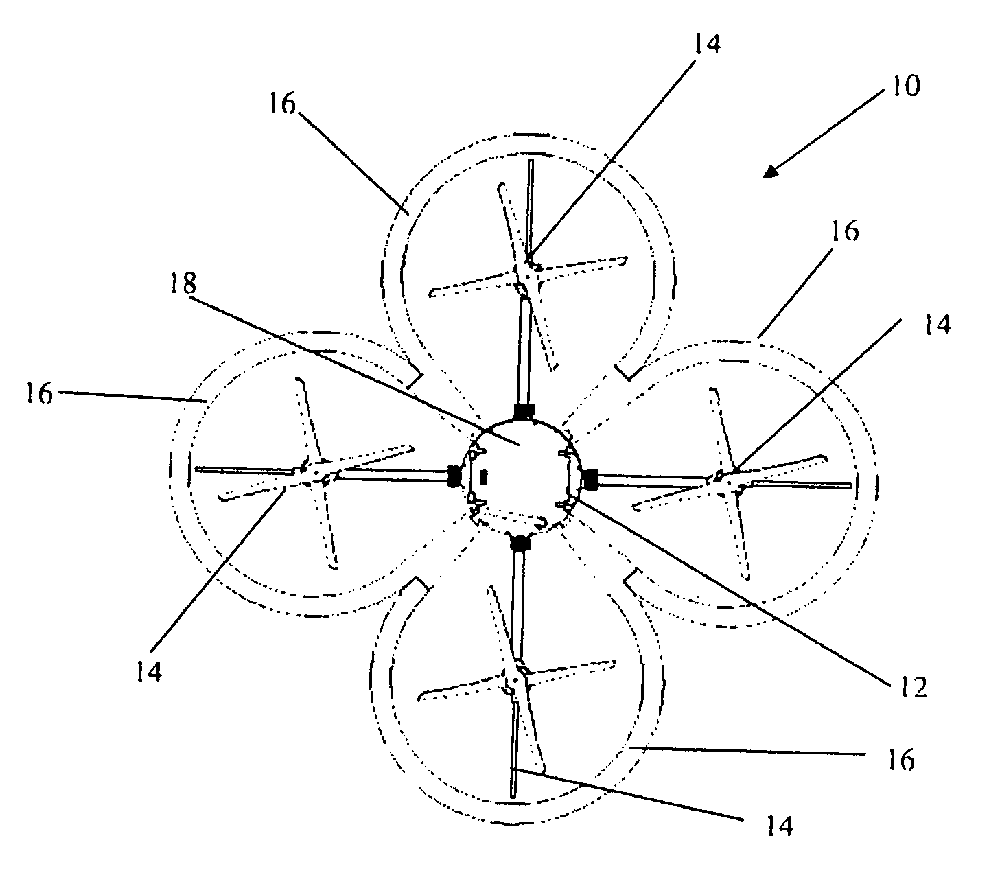
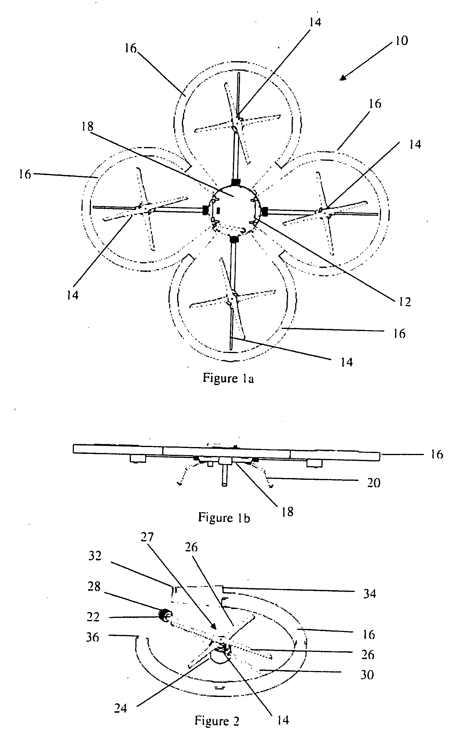
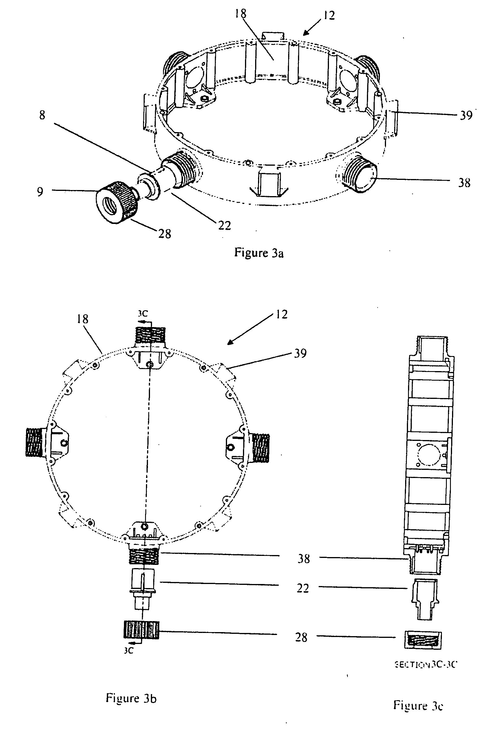
[0020]Generally, the present invention provides a novel hovering aerial vehicle. Turning to FIGS. 1a and 1b, a top view and a side view of the aerial vehicle are shown, respectively. The aerial vehicle 10 includes a central pod 12 to which a set of rotor arm assemblies 14 are connected. Along with this physical connection, there is an electrical connection between each rotor arm assembly 14 and the central pod 12 to provide power, control and communications capabilities therebetween. Surrounding each of the set of rotor arm assemblies 14 is a protective shroud 16. In the current embodiment, there is an individual shroud 16 for each of the rotor arm assemblies 14. A schematic diagram of a rotor arm assembly 14 and protective shroud 16 is shown in FIG. 2 which will be described in more detail below. The central pod 12 provides control, communications and data acquisition capabilities as well as a mechanical support structure such as frame 18 for itself and the rotor arm assemblies 14....


PUM


Abstract

The invention provides a hovering aerial vehicle with removable rotor arms and protective shrouds. Removing the shrouds reduces the weight of the vehicle and increases flight time. Removing the rotor arms makes the vehicle easier to transport. Removable rotor arms also simplify field repair or replacement of damaged parts.

Description

CROSS REFERENCE TO RELATED APPLICATIONS[0001]This application claims the benefit of priority of U.S. Provisional Patent Application No. 61 / 127,638 filed May 15, 2008 which is incorporated herein by reference in its entirety.FIELD OF THE INVENTION[0002]The present invention relates generally to aerial vehicles. More particularly, the present invention relates to an aerial vehicle with removable arms.BACKGROUND OF THE INVENTION[0003]Remote controlled drones with camera capability have been known for many years. These drones are used to provide visual reconnaissance for areas which are typically inaccessible by humans. These types of drones include a hovering aerial vehicle which is lifted and controlled by independently driven rotors or propellers. By varying the thrust generated by each of the rotors, the orientation and speed of the vehicle can be controlled. Various designs have been proposed for such an aerial vehicle, the primary requirement of which is to rigidly mount the rotor...

Claims


Application Information

Patent Timeline
Patent Type & Authority Applications(United States)
IPC IPC(8): B64C27/08
CPCA63H27/12B64C39/024B64C2201/108B64C2201/042B64C2201/088B64C2201/027B64U10/13B64U70/80B64U50/19B64U30/20
Inventor KROETSCH, DAVIDPEASGOOD, MIKEBRUBACHER-CRESSMAN, DALECHERLER, CRISTIANMARCHETTI, STEPHEN
Owner AERYON LABS
Why Eureka
Try Eureka