Detection target identifying/position estimating system, its method, and program

a technology of detection target and position estimation, applied in wave based measurement systems, instruments, reradiation, etc., can solve problems such as limit must be put, rfid system is not fully capable, and utilization environment or utilization method cannot be fully utilized

Inactive Publication Date: 2009-11-19
NEC CORP
View PDF2 Cites 12 Cited by
  • Summary
  • Abstract
  • Description
  • Claims
  • Application Information

AI Technical Summary

Benefits of technology

[0029]The present invention exhibits an excellent effect that a detection of the detection target is stabilizedly m

Problems solved by technology

The first point at issue is that a limit has to be put to a utilization environment or a utilization method so as to stabilize the detection in the RFID system.
The reason is that the conventional RFID system is not capable of completely solving the erroneous detection or the detection omission in all of the multifarious utilization environments or utilization methods, and so as to f

Method used


Image

  • Detection target identifying/position estimating system, its method, and program
  • Detection target identifying/position estimating system, its method, and program
  • Detection target identifying/position estimating system, its method, and program

Examples


exemplary example 1

AN EXEMPLARY EXAMPLE 1

[0089]An exemplary example 1 that corresponds to this exemplary embodiment described above will be explained.

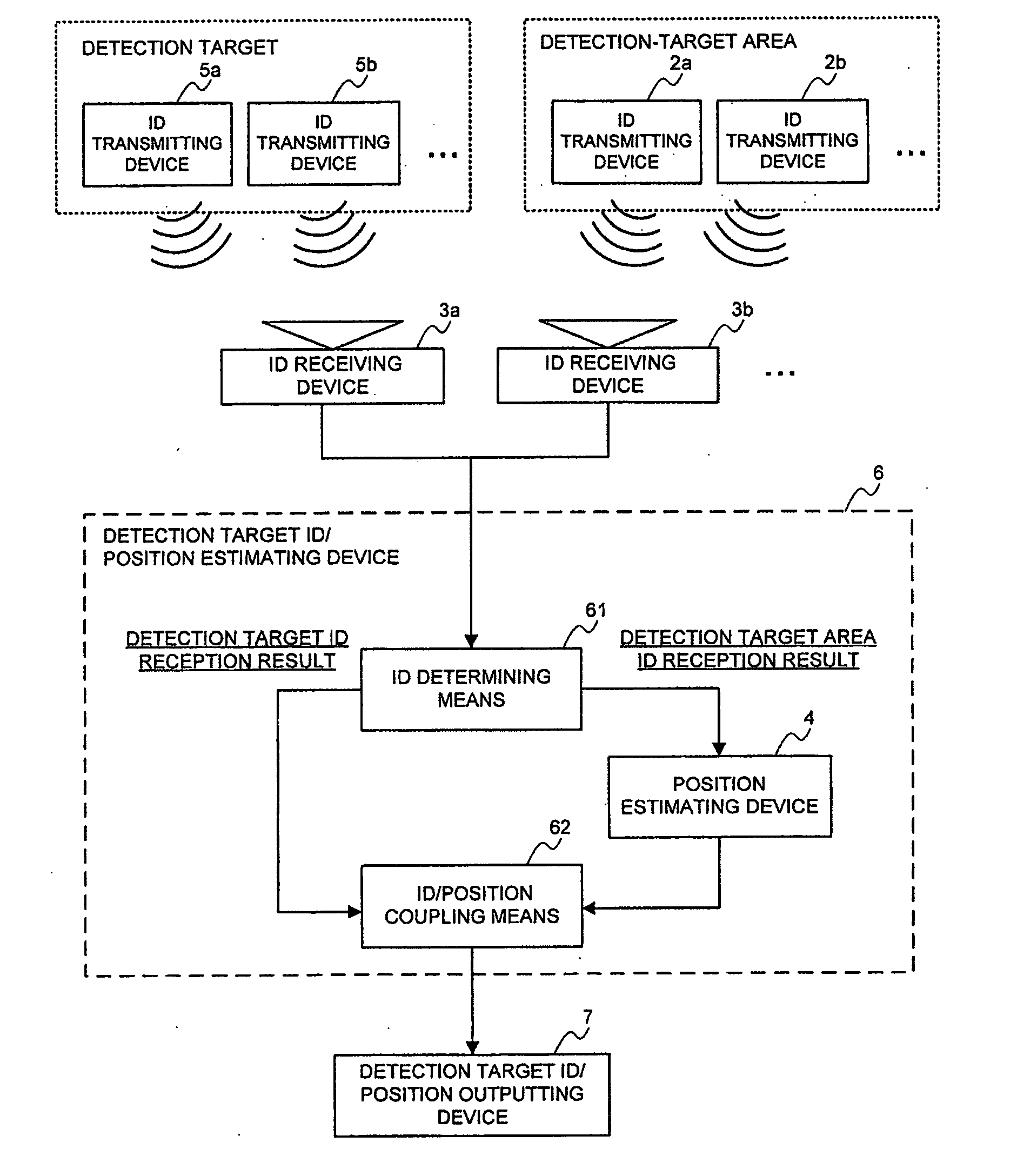
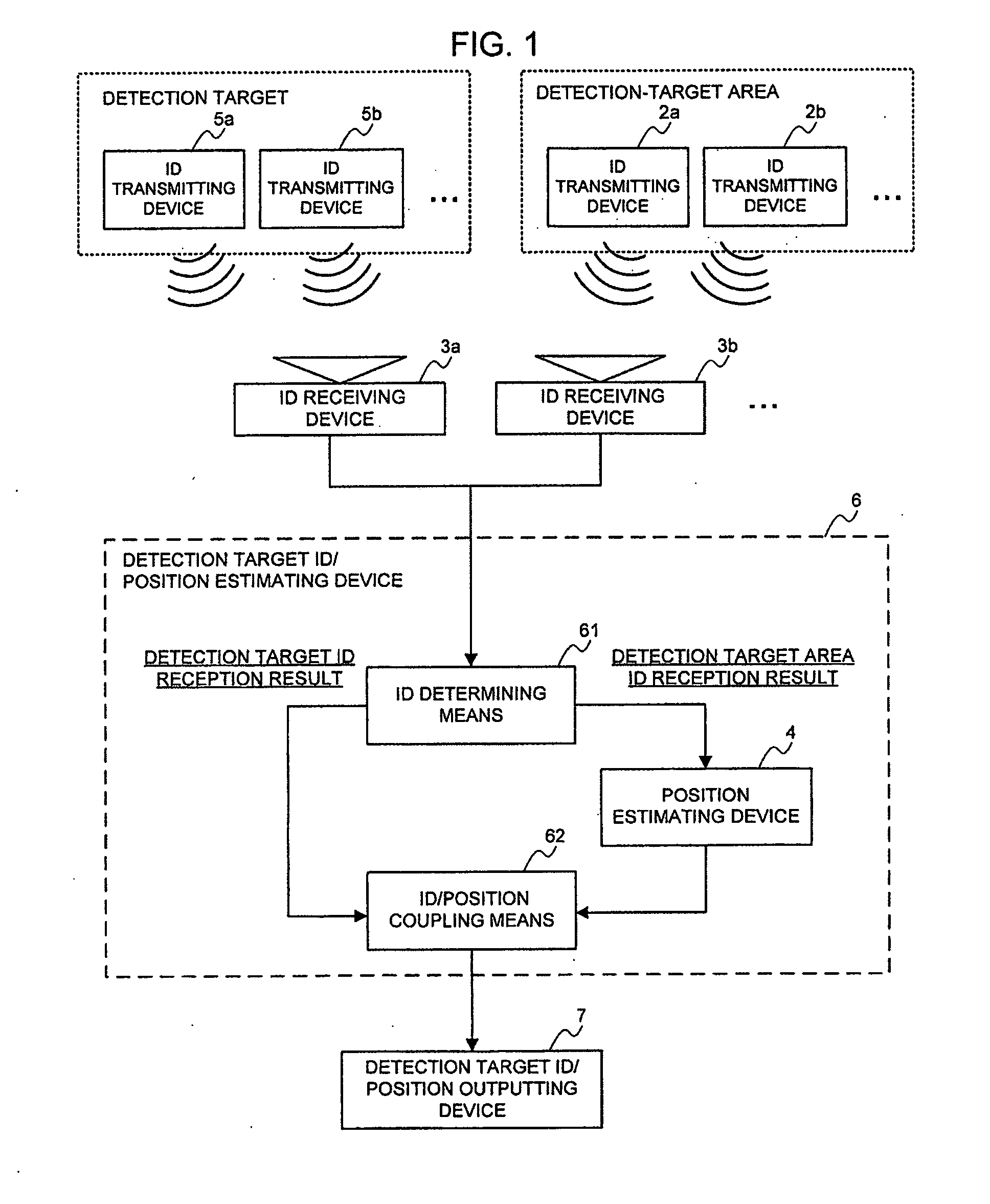
[0090]This exemplary example includes an active type RFID tag that employs a button cell as a power source to transmit an inherent ID, which it holds, for each constant time (for example, 0.5 sec.) with radio communication as the detection-target-area ID transmitting devices 2a and 2b, and the detection-target ID transmitting devices 5a and 5b, and an RFID reader that receives the IDs from the detection-target-area ID transmitting devices 2a and 2b, and the detection-target ID transmitting devices 5a and 5b and is capable of measuring the reception intensity (256-stage integral values ranging 0 to 255) as the ID receiving devices 3a and 3b.

[0091]The detection target ID / position estimating device 6 is realized with a personal computer, and a display is employed as the detection target ID / position outputting device 7. The personal computer includes a cent...


PUM


Abstract

Information from one or more transmitters installed in a detection object area is received. The reception feature value of when a detection object is present in a predetermined position of the detection object area is measured. A reception pattern of when the detection object is present in the predetermined position is formed. The reception pattern is compared with reference reception patterns, and the presence position corresponding to the reference reception pattern most approximate to the reception pattern is acquired from a reference reception pattern database where the presence positions of the detection object and the reference reception patterns of when the detection object is present in the presence positions are associated with one another. The presence position of the detection object is estimated according to the acquired presence position. The estimated presence position of the detection object is associated with received detection object identification information.

Description

APPLICABLE FIELD IN THE INDUSTRY[0001]The present invention relates to a detection target identification / position estimation technology of identifying inherent information of a detection target such as a person and a thing, estimating an existence position of its detection target, and causing the inherent information of the detection target and its existence position to correspond to each other.BACKGROUND ART[0002]Conventionally, an RFID (Radio Frequency Identification) system, which is configured of a device holding an inherent ID and a device reading off it, has a problem that an erroneous detection and a detection omission occur and resultantly the detection of the ID becomes unstable due to influences such as an antenna directivity of an ID holding device and an ID reading device, an disorder of a radio wave environment caused by a multipath etc., a change in an antenna characteristic caused by a person or a thing to which the ID holding device has been affixed, and radio wave n...

Claims


Application Information

Patent Timeline
IPC IPC(8): H04Q5/22G01S5/02
CPCG01S5/0252G01S13/825G06K2017/0045G01V15/00G01S13/876G01S5/02521
Inventor KONISHI, YUSUKENAKAO, TOSHIYASU
Owner NEC CORP
Why Eureka
Try Eureka