
Method of Retrieving a Blood Clot Filter

a filter device and blood clot technology, applied in the field of thrombosis capture and retrieval methods, can solve the problems of reducing the retrieval effort, reducing the retrieval efficiency, and prone to tilting and misalignment of the design,

Inactive Publication Date: 2009-11-19
ANGIODYNAMICS INC
View PDF26 Cites 6 Cited by
  • Summary
  • Abstract
  • Description
  • Claims
  • Application Information

AI Technical Summary

Benefits of technology

The present invention provides a retrivable blood clot filter that can be easily removed from the body. The filter includes a filter section with a plurality of filter legs, a releasable lock, and an alignment section. The alignment section has a plurality of alignment ribs with releasable upstream ends that can slide through the endothelial tissue that may have grown around the alignment ribs during retrieval of the filter. The invention also provides a method of retrieving the filter by capturing the alignment section with a retrieval device and releasing the releasable upstream ends of the alignment ribs. The technical effects of the invention include improved blood clot filtering and ease of removal from the body.

Problems solved by technology

Although conical filter configurations currently available on the market provide optimal filtering capabilities, these designs are prone to tilting and misalignment.
When not in proper alignment, filtering ability is compromised.
If the filter tilts, this may result in the retrieval hook coming in contact with the vessel wall, making retrieval efforts more difficult or even preventing removal of the filter device.
Tilting may also cause disruption of laminar blood flow, decrease in lysing of captured clots, or thrombus build-up and occlusion of the filter.
While free arm centering designs ensure that the conical filtering section generally remains centered within the vessel, these designs are disadvantageous in that the free arms are prone to vessel perforation, fracture and in some cases misalignment due asymmetrical spacing of the free arms.
Moreover, occasionally, when attempting to snare the alignment arms, they will become bent upwards making the retrieval of the filter even more difficult.
Although overcoming problems associated with free arm centering structures, filters designed with closed loop structures are difficult to retrieve from the vessel, particularly if a portion of the alignment structure has become incorporated into the vessel wall by endothelial overgrowth.
A band of endothelial tissue over a filter segment makes retrieval of the filter from the vessel more difficult, especially those filters designed with a closed loop configuration.

Method used


Image

  • Method of Retrieving a Blood Clot Filter
  • Method of Retrieving a Blood Clot Filter
  • Method of Retrieving a Blood Clot Filter

Examples


Embodiment Construction

[0040]For the purposes of the present application, the terms upstream and downstream refer to the direction of blood flow within a blood vessel. Accordingly, blood flows from an upstream direction towards a downstream direction. Also, it is important to note that although the filters disclosed herein are capable of being retrieved, they can be used as permanent filters without being retrieved.

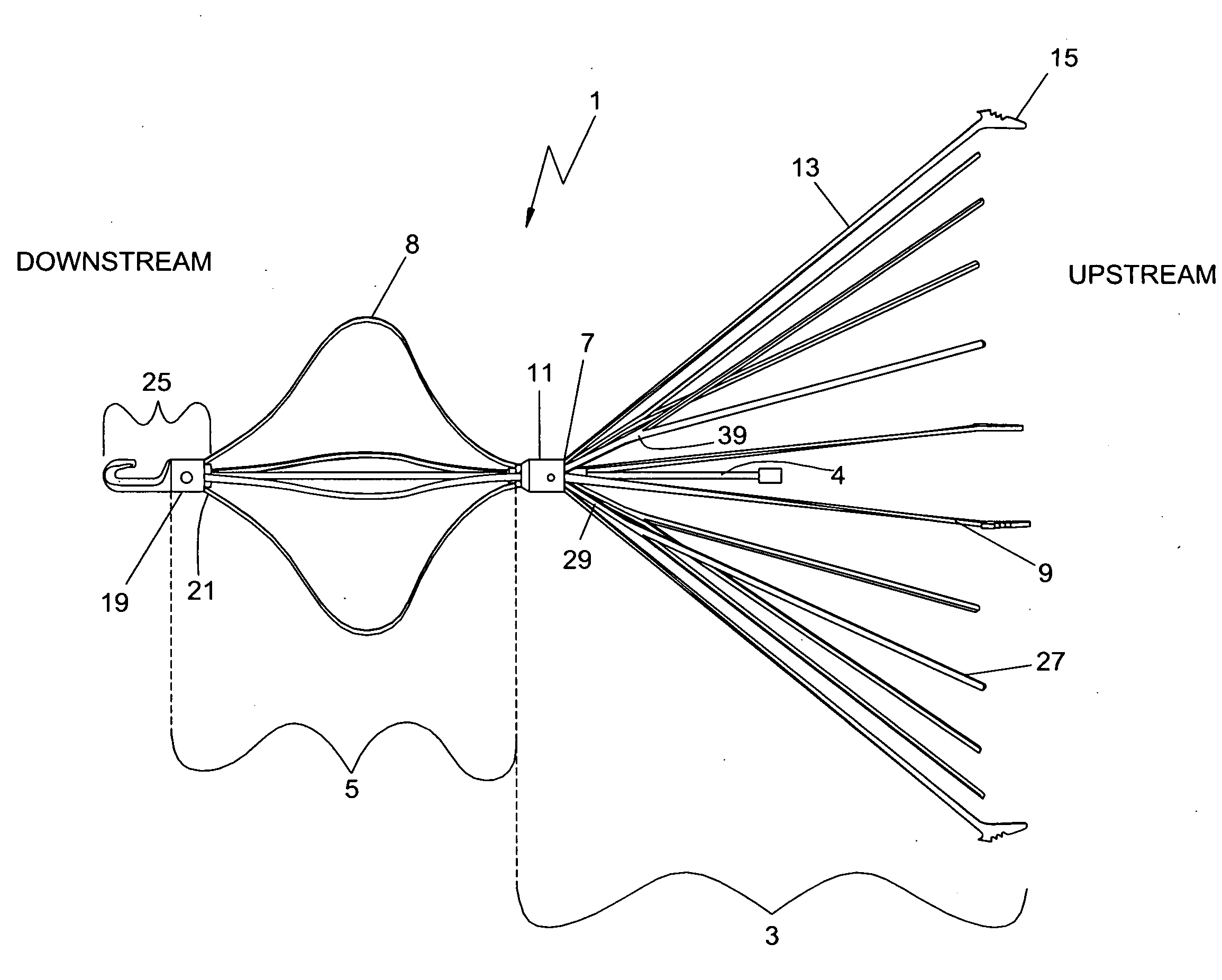
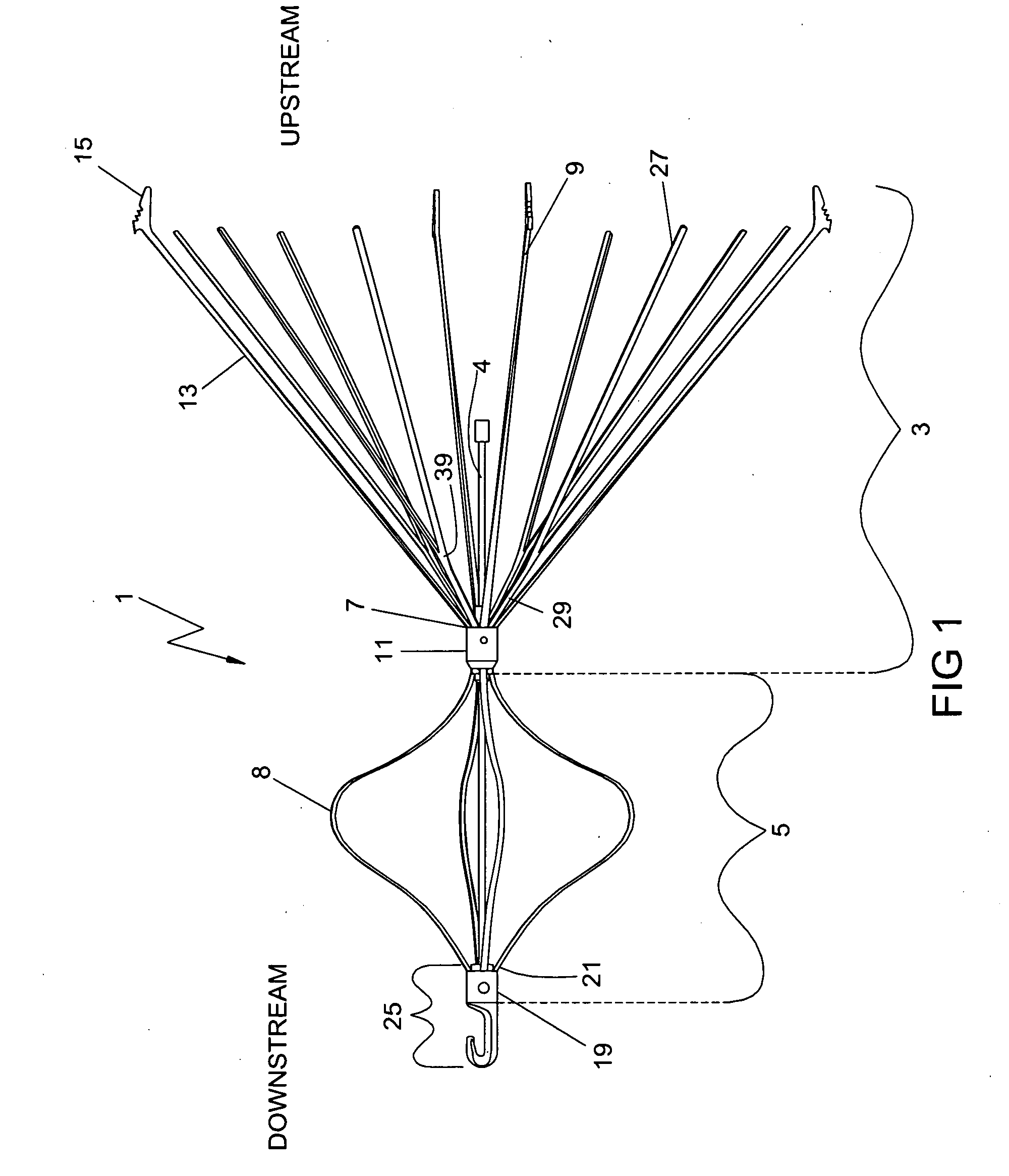
[0041]Referring to FIG. 1, there is shown an embodiment of the present invention in a plan view of an expanded vena cava filter device 1. When deployed in the path of the bloodstream, typically in the vena cava vein, the filter device 1 captures blood clots of a predetermined size and prevents them from traveling further downstream.

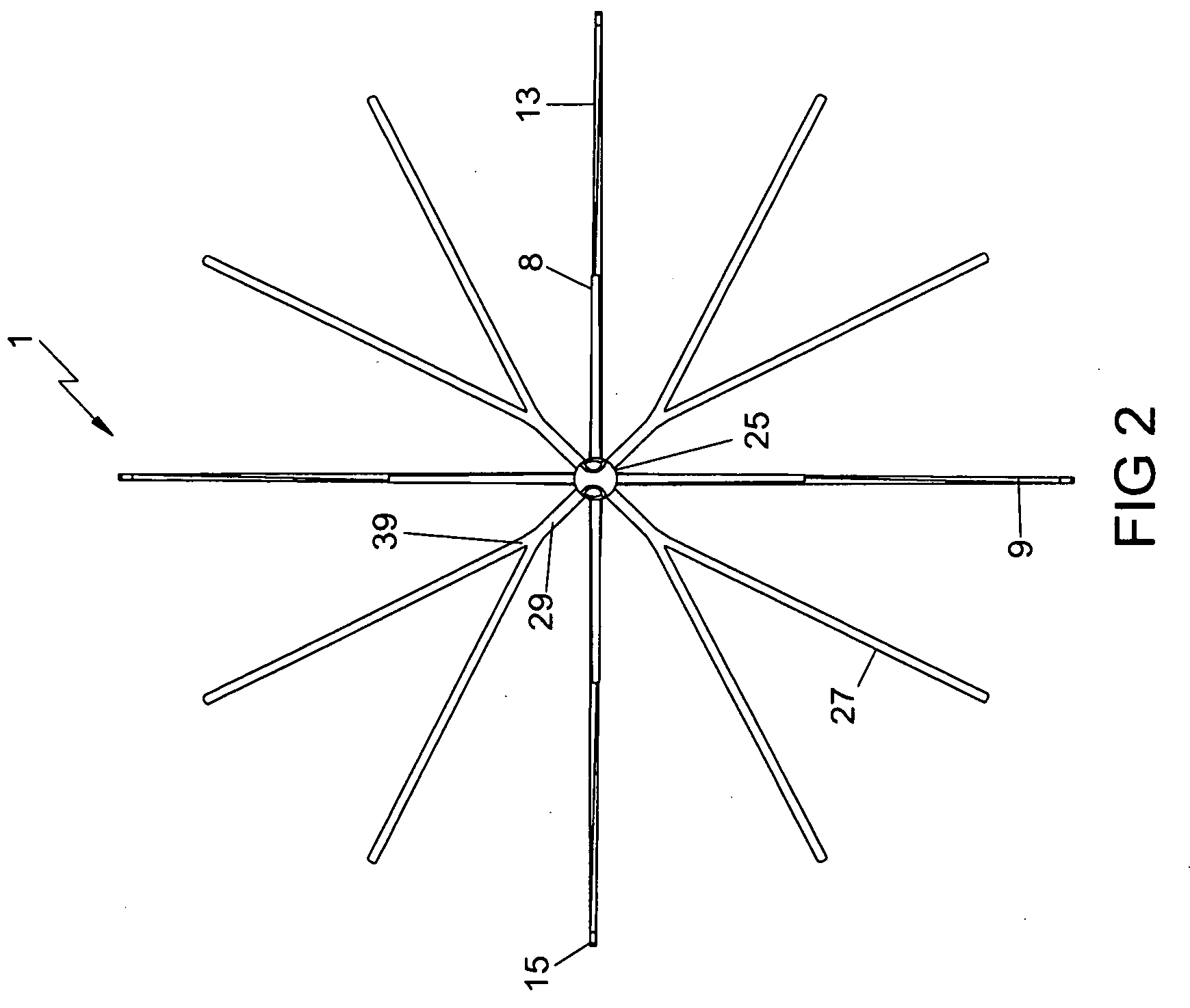
[0042]The vena cava filter device 1 is comprised of a conical filtering section 3, an alignment section 5, a center shaft / rod 4 and a retrieval hook subassembly 25. The conical filtering section 3 captures and lyses blood clots, anchors the filter device 1, and preve...


PUM


Abstract

A compact retrievable blood clot filter has a filter section, a releasable lock and an alignment section connected to the filter section. Alignment ribs of the alignment section have releasable upstream ends that are locked to the filter by the releasable lock. The releasable upstream ends of the alignment ribs are capable of being released from the releasable lock so that during retrieval of the filter, the alignment ribs can slide through the endothelial tissue that may have grown around the alignment ribs.

Description

CROSS-REFERENCE TO RELATED APPLICATIONS[0001]This is a divisional application of U.S. application Ser. No. 11 / 625,723, filed Jan. 22, 2007, which claims priority to U.S. provisional patent application Ser. No. 60 / 760,600 filed on Jan. 20, 2006 and U.S. provisional patent application Ser. No. 60 / 862,670 filed on Oct. 24, 2006, all of which are incorporated herein by reference in their entireties.FIELD OF THE INVENTION[0002]The present invention relates to a medical device apparatus and method for the capturing of thrombus. More particularly, the present invention relates to a retrievable vena cava filter device and a method of retrieving the same from a vessel.BACKGROUND OF THE INVENTION[0003]Vena cava filters are used to capture potentially fatal blood clots at an anatomical location where they may pose less risk of pulmonary emboli for the patient. Since the vast majority of pulmonary emboli originate from the lower body, filters are mainly placed in the inferior vena cava.[0004]Th...

Claims


Application Information

Patent Timeline
Patent Type & Authority Applications(United States)
IPC IPC(8): A61M29/00A61F2/06
CPCA61F2/01A61F2002/011A61F2230/0093A61F2230/005A61F2230/0067A61F2002/016A61F2/011A61F2/012
Inventor CARTIER, WILLIAM A.BEYER, THEODORE J.APPLING, WILLIAM M.PALMA, GIORGIO DI
Owner ANGIODYNAMICS INC
Learn More