Surgical Composite Barbed Suture

Inactive Publication Date: 2009-11-19
BOSTON SCI SCIMED INC
View PDF37 Cites 106 Cited by
  • Summary
  • Abstract
  • Description
  • Claims
  • Application Information

AI Technical Summary

Benefits of technology

[0009]In another embodiment, a medical device includes a first tissue anchor including a retaining member extending therefrom. The medical device includes a second tissue anchor including a retaining member extending therefrom. The medical device includes a filament coupled to the first tissue anchor and coupled to the second tissue anchor. The medical device is configured to be inser

Problems solved by technology

The process of reducing the width of the suture al

Method used


Image

  • Surgical Composite Barbed Suture
  • Surgical Composite Barbed Suture
  • Surgical Composite Barbed Suture

Examples


Embodiment Construction

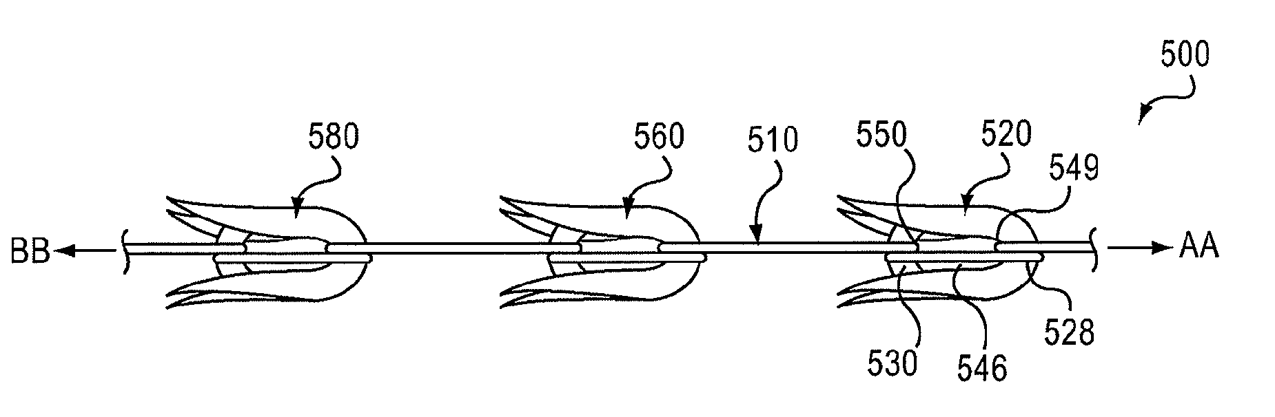
[0020]The medical device described herein can be inserted into a body of a patient, such as within bodily tissue. For example, the medical device can be configured as a suture that can couple a first bodily tissue to a second bodily tissue. In some embodiments, the medical device can help provide support for a urethra or other anatomical structure. The medical device or suture includes multiple tissue anchors and a filament that is coupled to each of the tissue anchors. In some embodiments, the tissue anchors have the same orientation with respect to the filament when the filament is in a linear configuration. The suture can be inserted into bodily tissue in a first direction. The suture, however, is prevented from moving in a second direction different than the first direction due to the orientation and structure of the tissue anchors.

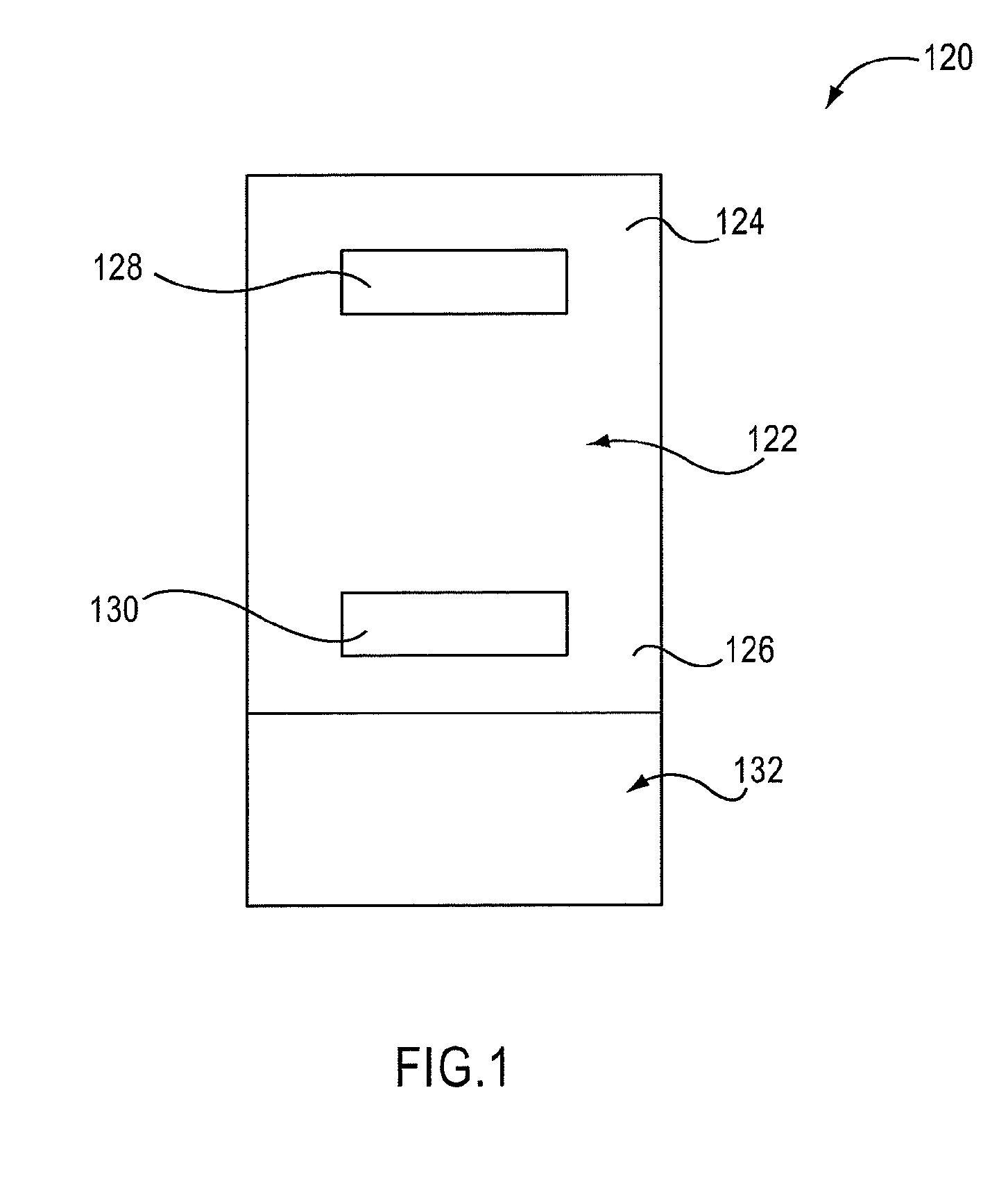
[0021]FIG. 1 is a schematic illustration of a tissue anchor according to an embodiment of the invention. An apparatus 120 (also referred to herein as...


PUM


Abstract

In one embodiment, a medical device includes an elongate member configured to be inserted into a body. The elongate member has a first end portion and a second end portion opposite the first end portion. The elongate member includes a retaining member extending from the elongate member. The retaining member is configured to anchor the elongate member with respect to bodily tissue. The first end portion of the elongate member includes a coupling portion configured to be coupled to a filament. The second end portion of the elongate member includes a coupling portion configured to be coupled to the filament.

Description

CROSS-REFERENCE TO RELATED APPLICATION[0001]This application claims priority to U.S. Provisional Patent Application Ser. No. 61 / 071,726, entitled “Surgical Composite Barbed Suture,” filed May 14, 2008, the disclosure of which is incorporated herein by reference in its entirety.BACKGROUND[0002]This invention relates to a medical device and more particularly to a suture including multiple tissue anchors.[0003]The disclosed embodiments have application to a wide variety of surgical procedures including those that require high anchoring strength. For example, one such procedure is directed to female urinary incontinence and involves insertion of a suture to be fixed to bodily tissue under and / or lateral to the urethra to reconstitute the ligamentary support for the urethra. Generally, the suture is inserted into two or more body tissues to couple the body tissues tightly together without knotting the suture.[0004]A known suture device includes an elongated body and a plurality of axiall...

Claims


Application Information

Patent Timeline
IPC IPC(8): A61B17/04A61B17/08
CPCA61B17/06166A61B2017/06176A61B2017/0458A61B2017/0412
Inventor OSTROVSKY, ISAACDAVOUDI, HAMIDSLANDA, JOZEF
Owner BOSTON SCI SCIMED INC
Why Eureka
Try Eureka