Lead assembly and related methods

a defibrillator and lead technology, applied in the field of implantable defibrillator leads, can solve the problems of uncovered coils that are subject to future fibrotic entanglement, and can be extremely difficult to remov

Inactive Publication Date: 2009-11-19
CARDIAC PACEMAKERS INC
View PDF26 Cites 11 Cited by
  • Summary
  • Abstract
  • Description
  • Claims
  • Application Information

AI Technical Summary

Benefits of technology

[0006]Certain examples include a lead comprising a lead body, at least one shocking coil electrode, and a fibrosis-limiting material. The lead body extends from a lead proximal end portion to a lead distal end portion and may optionally include an inner insulating layer and an outer insulating layer. At least one shocking coil electrode is disposed along the lead body, for example, but not limited to, at one or both of the lead intermediate portion or the lead distal end portion. The shocking coil electrode optionally includes one or more treated portions, such as laser welded portions. The coil electrode is a close wound tri-filar or greater coil. The fibrosis-limiting material coaxially surrounds, at least in part, the at least one shocking coil electrode.

Problems solved by technology

Once implanted, the exposed shocking coil electrodes often become entangled with fibrosis (i.e., a capsule of inactive tissue which grows into the exposed coils) with the end result being that a chronically implanted lead can be extremely difficult to remove by the application of tensile force to the lead proximal end.
Over time, situations may arise which require the removal and replacement of an implanted defibrillator lead.
When subjected to shear loads, such as during lead implantation procedures, the fibrosis-limiting material may separate from the associated shocking coil electrode or the shocking coil electrodes themselves may separate from the lead body or deform, thereby leaving uncovered coils that are subject to future fibrotic entanglement.

Method used


Image

  • Lead assembly and related methods
  • Lead assembly and related methods
  • Lead assembly and related methods

Examples


Embodiment Construction

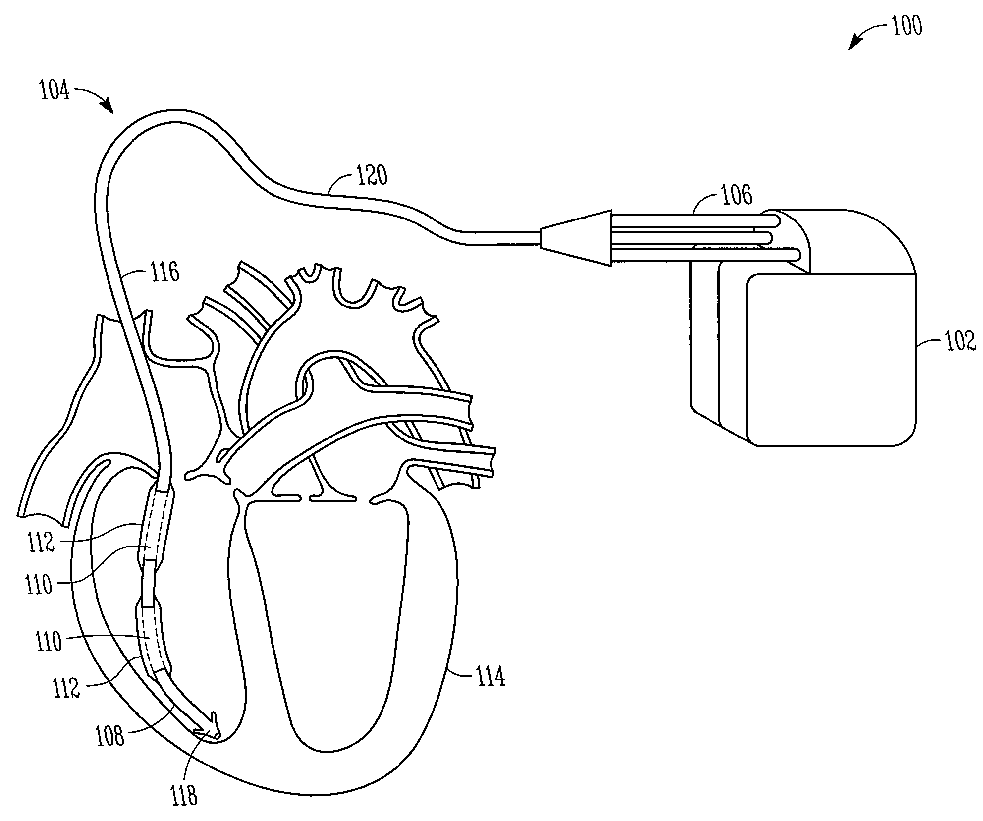
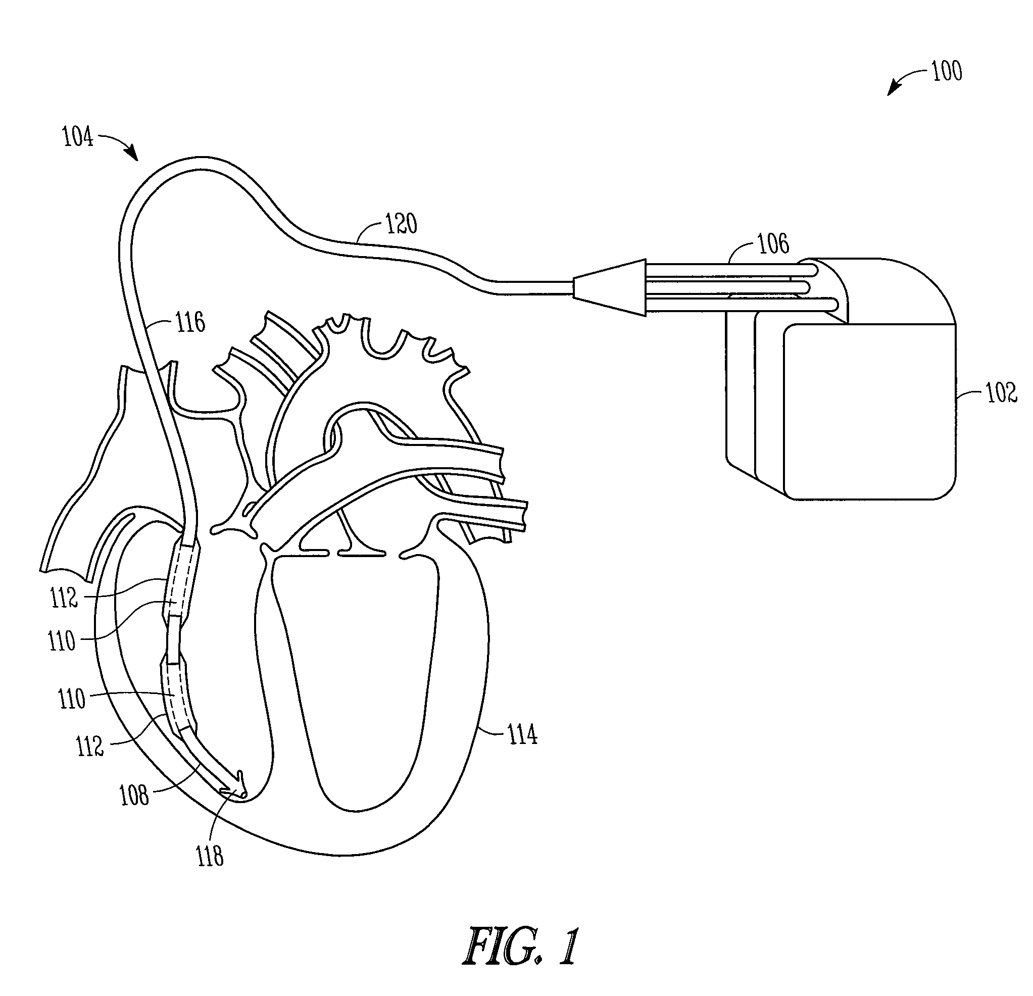
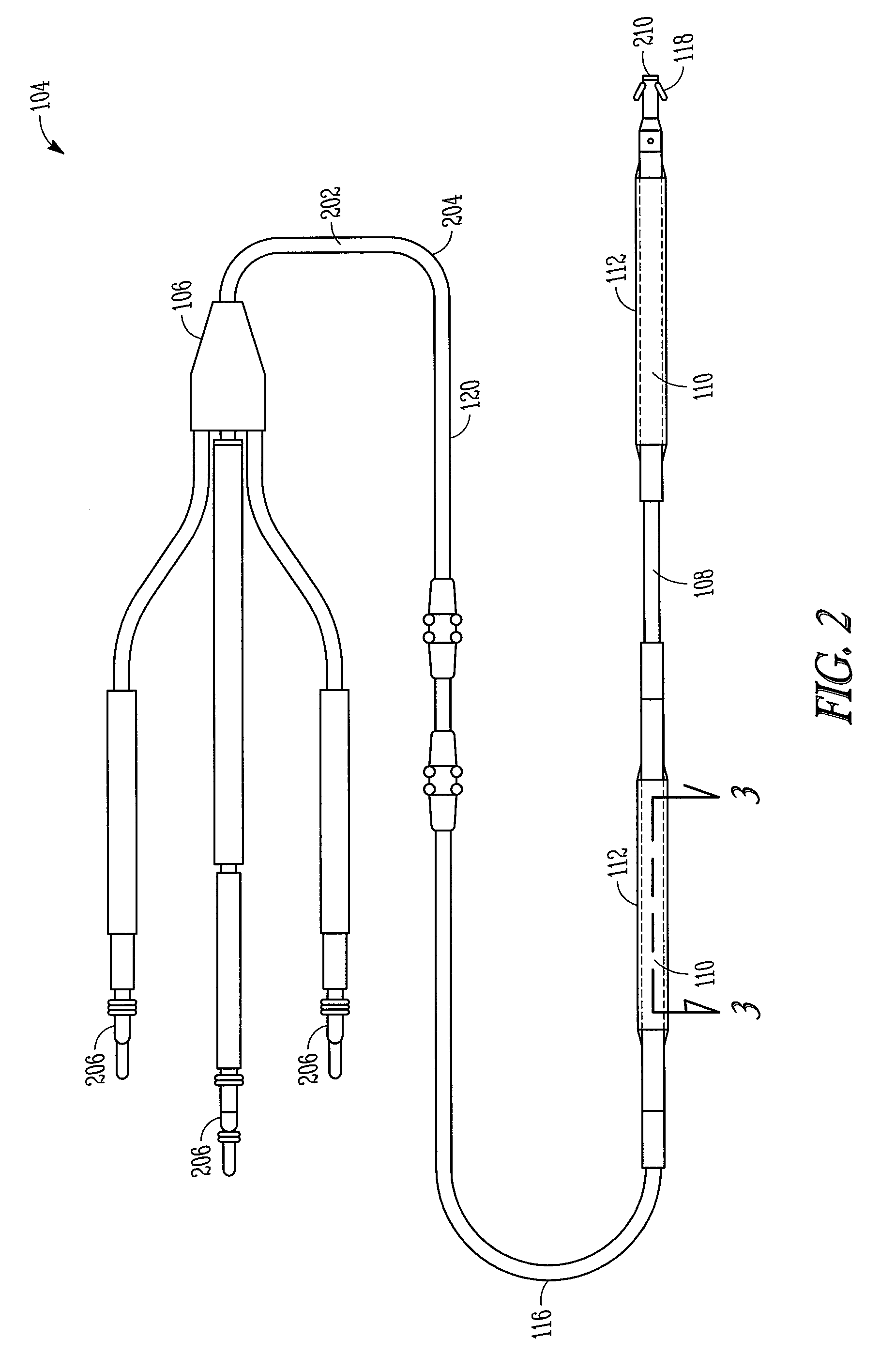
[0016]The following detailed description includes references to the accompanying drawings, which form a part of the detailed description. The drawings show, by way of illustration, specific embodiments in which the present leads and methods may be practiced. These embodiments, which are also referred to herein as “examples,” are described in enough detail to enable those skilled in the art to practice the present leads and methods. The embodiments may be combined, other embodiments may be utilized or structural or logical changes may be made without departing from the scope of the present leads and methods. The following detailed description is, therefore, not to be taken in a limiting sense, and the scope of the present leads and methods is defined by the appended claims and their legal equivalents.

[0017]In this document, the terms “a” or “an” are used to include one or more than one, and the term “or” is used to refer to a nonexclusive “or” unless otherwise indicated. In addition,...


PUM

PropertyMeasurementUnit
perimeteraaaaaaaaaa
tensile forceaaaaaaaaaa
electrical activityaaaaaaaaaa

Abstract

Defibrillator lead designs and methods for manufacturing a lead including attachment strength between a fibrosis-limiting material covering, a shocking coil electrode, and an implantable lead body are disclosed herein. The shocking coil electrode includes a close wound tri-filar or greater coil.

Description

RELATED APPLICATIONS[0001]This application claims the benefit under 35 U.S.C. 119(e) of U.S. Provisional Patent Application Ser. No. 61 / 051,266, filed on May 7, 2008, which is incorporated herein by reference in it entirety.TECHNICAL FIELD[0002]This document pertains generally to implantable defibrillator leads.BACKGROUND[0003]Cardiac and other defibrillation systems typically include an implantable medical device (IMD), such as a pulse generator, electrically connected to the heart by at least one implantable defibrillator lead. More specifically, an implantable defibrillator lead provides an electrical pathway between the IMD, connected to a proximal end of the lead, and cardiac tissue, in contact with a distal end of the lead. In such a manner, electrical stimulation (e.g., in the form of one or more shocks or countershocks) emitted by the IMD may travel through the implantable defibrillator lead and stimulate the heart via one or more exposed, helically wound shocking coil elect...

Claims


Application Information

Patent Timeline
Patent Type & Authority Applications(United States)
IPC IPC(8): A61N1/05H01F7/06
CPCA61N1/056Y10T29/49071A61N1/0563
Inventor LYNN, MARK C.
Owner CARDIAC PACEMAKERS INC
Why Eureka
Try Eureka