
Enclosures for LED circuit boards

a technology of led circuit boards and enclosures, which is applied in the direction of fixed installation, lighting and heating equipment, lighting support devices, etc., can solve the problems of preventing easy access to led boards by refractivetors, affecting the efficiency and effectiveness of fixtures, and additional risks for handlers, so as to achieve the effect of easy separation of enclosures

Active Publication Date: 2009-11-26
ABL IP HLDG
View PDF40 Cites 87 Cited by
  • Summary
  • Abstract
  • Description
  • Claims
  • Application Information

AI Technical Summary

Benefits of technology

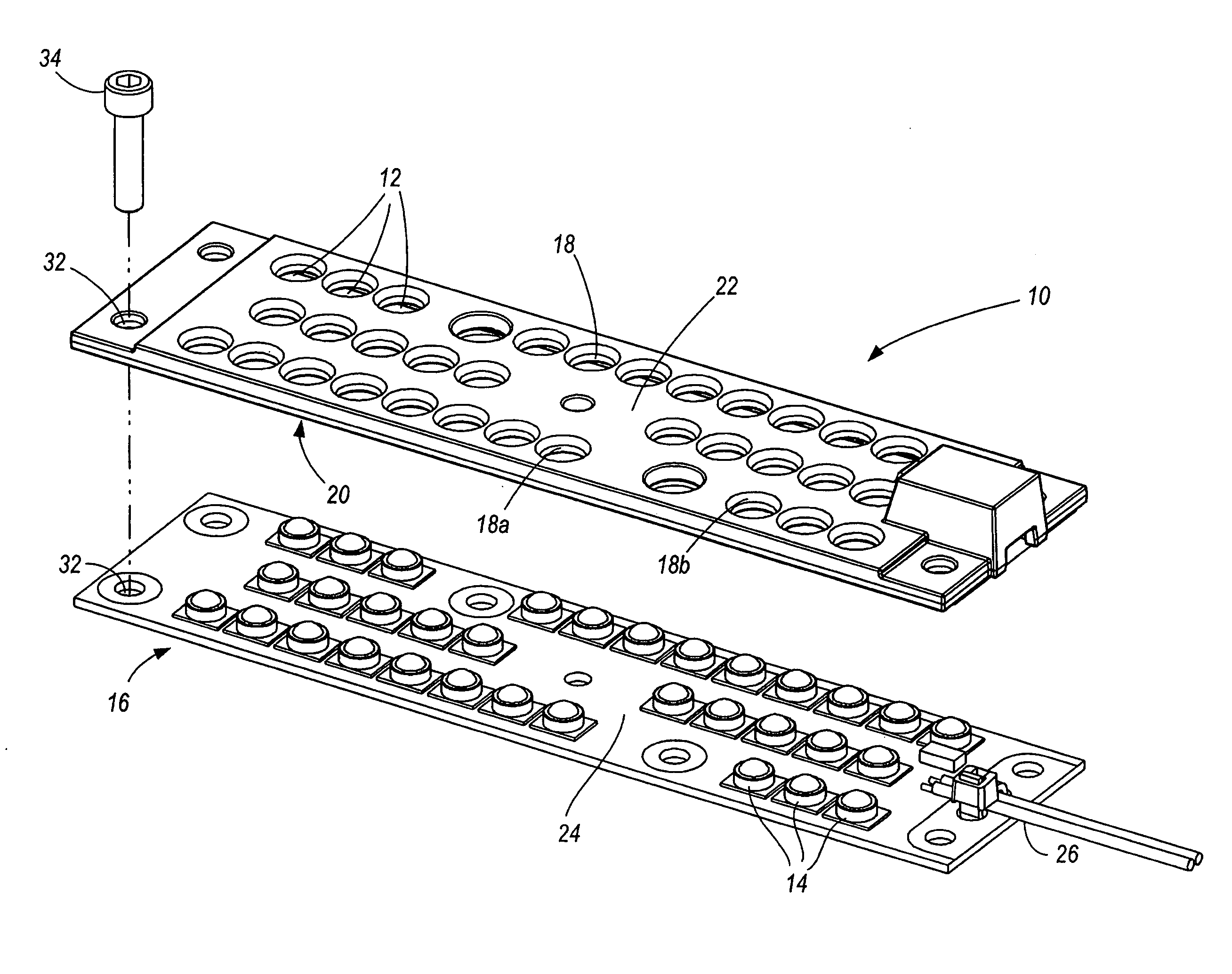
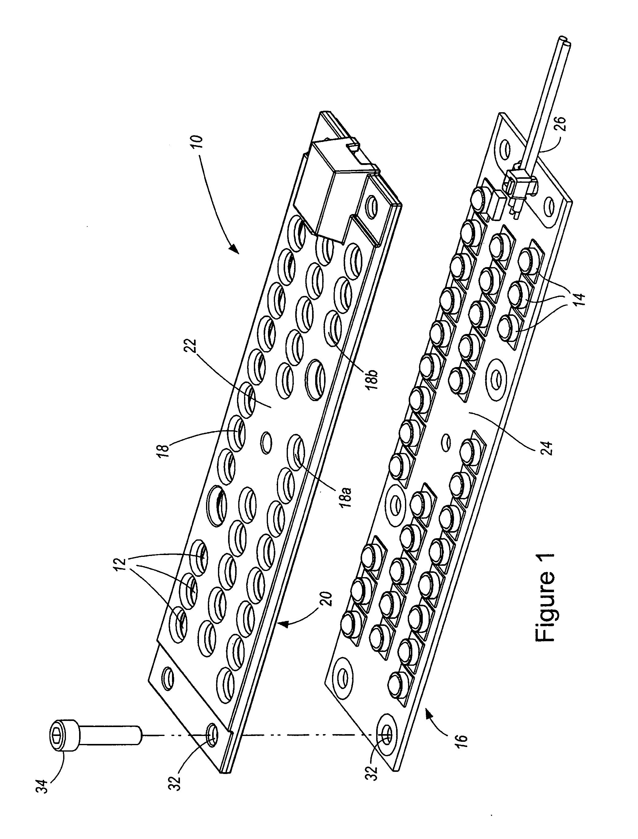
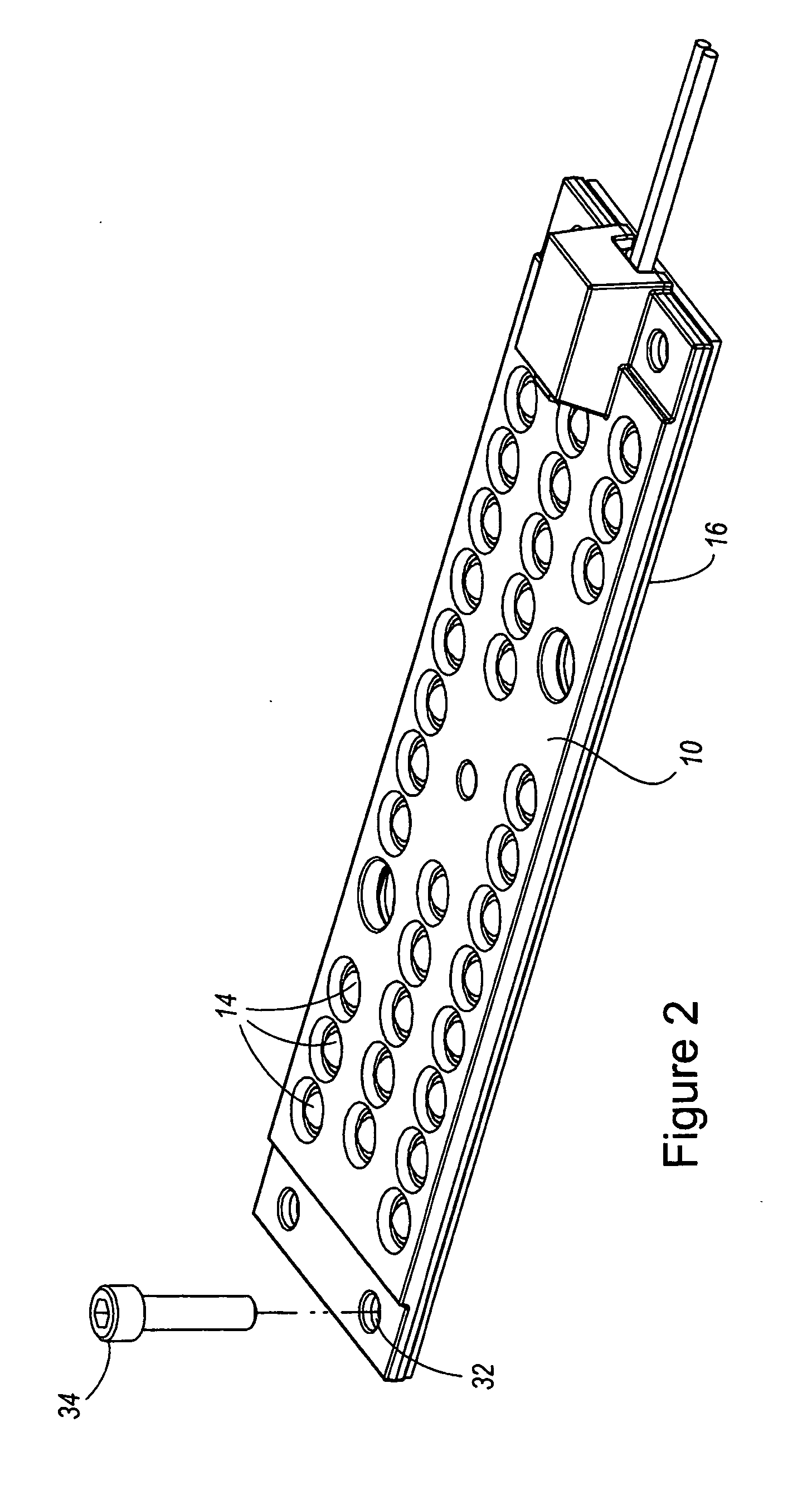
[0004]Embodiments of this invention provide an enclosure for an LED circuit board. The enclosure is manufactured from a flame resistant material and includes LED apertures through which the LEDs mounted on an LED circuit board may pass. The enclosure is designed to be positioned on the LED circuit board so that, when so positioned, the LEDs extend at least partially through the LED apertures in the enclosure. When the enclosure is positioned on the board, portions of its lower surface contact the upper surface of the board. Various fixation / retention methods may be used to retain the enclosure in position relative to the circuit board. It is preferable that such methods allow for the relatively easy separation of the enclosure from the board.

Problems solved by technology

However, the voltage necessary to power an LED circuit board for use in lighting fixtures oftentimes renders the board a non-Class 2 component as defined by the National Electric Code (“NEC”).
The refractor thereby prevents easy access to the LED board within the fixture.
However, refractors are traditionally made of glass, which, while 5VA compliant, can be prone to break and thereby present additional risks to handlers.
Moreover, because the light emitted from the LEDs in such fixtures must pass through the glass refractor, some of the light is lost, thereby impacting the efficiency and effectiveness of the fixture.
While metal is also a 5VA compliant material, use of it in the fixture elevates the risk of electric shock and, given that it is nontransparent, impedes the transmission of the light emitted from the LEDs.

Method used


Image

  • Enclosures for LED circuit boards
  • Enclosures for LED circuit boards
  • Enclosures for LED circuit boards

Examples


Embodiment Construction

[0004]Embodiments of this invention provide an enclosure for an LED circuit board. The enclosure is manufactured from a flame resistant material and includes LED apertures through which the LEDs mounted on an LED circuit board may pass. The enclosure is designed to be positioned on the LED circuit board so that, when so positioned, the LEDs extend at least partially through the LED apertures in the enclosure. When the enclosure is positioned on the board, portions of its lower surface contact the upper surface of the board. Various fixation / retention methods may be used to retain the enclosure in position relative to the circuit board. It is preferable that such methods allow for the relatively easy separation of the enclosure from the board.

BRIEF DESCRIPTION OF THE DRAWINGS

[0005]FIG. 1 is an exploded view of an enclosure according to one embodiment of the present invention and an LED circuit board.

[0006]FIG. 2 is a perspective view of the enclosure of FIG. 1 positioned on the LED c...


PUM


Abstract

Embodiments of this invention provide an enclosure for an LED circuit board. The enclosure is manufactured from a flame resistant material and includes LED apertures through which LEDs mounted on an LED circuit board may pass. The enclosure is designed to be positioned on the LED circuit board so that, when so positioned, the LEDs extend at least partially through the LED apertures in the enclosure. When the enclosure is positioned on the board, portions of its lower surface contact the upper surface of the board. Various fixation / retention methods may be used to retain the enclosure in position relative to the circuit board. It is preferable that such methods allow for the separation of the enclosure from the board.

Description

FIELD OF THE INVENTION[0001]Embodiments of the invention relate to non-flammable enclosures for LED circuit boards.BACKGROUND OF THE INVENTION[0002]The use of light emitting diodes (“LED”) in lighting fixtures to supply the desired illumination is becoming more prevalent. However, the voltage necessary to power an LED circuit board for use in lighting fixtures oftentimes renders the board a non-Class 2 component as defined by the National Electric Code (“NEC”). See NEC (specifically Section 725 and Table 11(B)) (2005), the entirety of which is herein incorporated by reference. Existing LED circuit boards which operate beyond the limits of Class 2 power are designated by UL as a “risk of fire” and must be contained. See UL 8750 (specifically section 3.17)(2008), the entirety of which is herein incorporated by reference. Containment requires that the LED board be enclosed so that a person cannot easily come into contact with the board. More specifically, the enclosure must be manufact...

Claims


Application Information

Patent Timeline
IPC IPC(8): F21V21/00
CPCF21K9/00F21V5/04F21V19/0035F21S8/026F21Y2101/02F21V25/12F21W2131/103F21Y2115/10
Inventor SHANER, JEFF
Owner ABL IP HLDG
Learn More