Modular Bag Filling Apparatus

a bag filling and module technology, applied in the direction of liquid handling, instruments, packaged goods, etc., can solve the problems of difficult or impossible to retrofit additional components onto most existing bag filling machines, difficult to eliminate components, and not easily adapt to suit the varying needs of users

Active Publication Date: 2009-12-03
SPIROFLOW SYST
View PDF37 Cites 10 Cited by
  • Summary
  • Abstract
  • Description
  • Claims
  • Application Information

AI Technical Summary

Benefits of technology

[0009]In yet another aspect the invention provides that the filling head support structure comprises a frame structure connected to an end of the second support member which is distal to said first support member, and wherein the filling head is rigidly secured to said frame structure.
[0010]In yet another aspect the invention provides that the frame structure comprises a framework of generally horizontal members to which the filling head is secured, wherein the filling head comprises a pair of concentric cylinders separated by an annular space.

Problems solved by technology

One disadvantage of existing bag filling machines is that they are not easily adapted to suit the varying needs of users.
In general, the inventors have found that it is difficult or impossible to retrofit additional components onto most existing bag filling machines.
Likewise, it may be difficult to eliminate components which are not required by a specific user.
This not only limits the range of choices available to the user, but can increase cost due to the fact that it may be necessary to design a separate filling machine for each application.
Furthermore, a user wishing to upgrade to a filling machine having enhanced features will be forced to purchase a new machine where retrofitting the additional components is not possible.
The inventors have also found that many filling machines employ weighing mechanisms which are unnecessarily complex.
This can result in poor reliability and high cost.

Method used


Image

  • Modular Bag Filling Apparatus
  • Modular Bag Filling Apparatus
  • Modular Bag Filling Apparatus

Examples


first embodiment

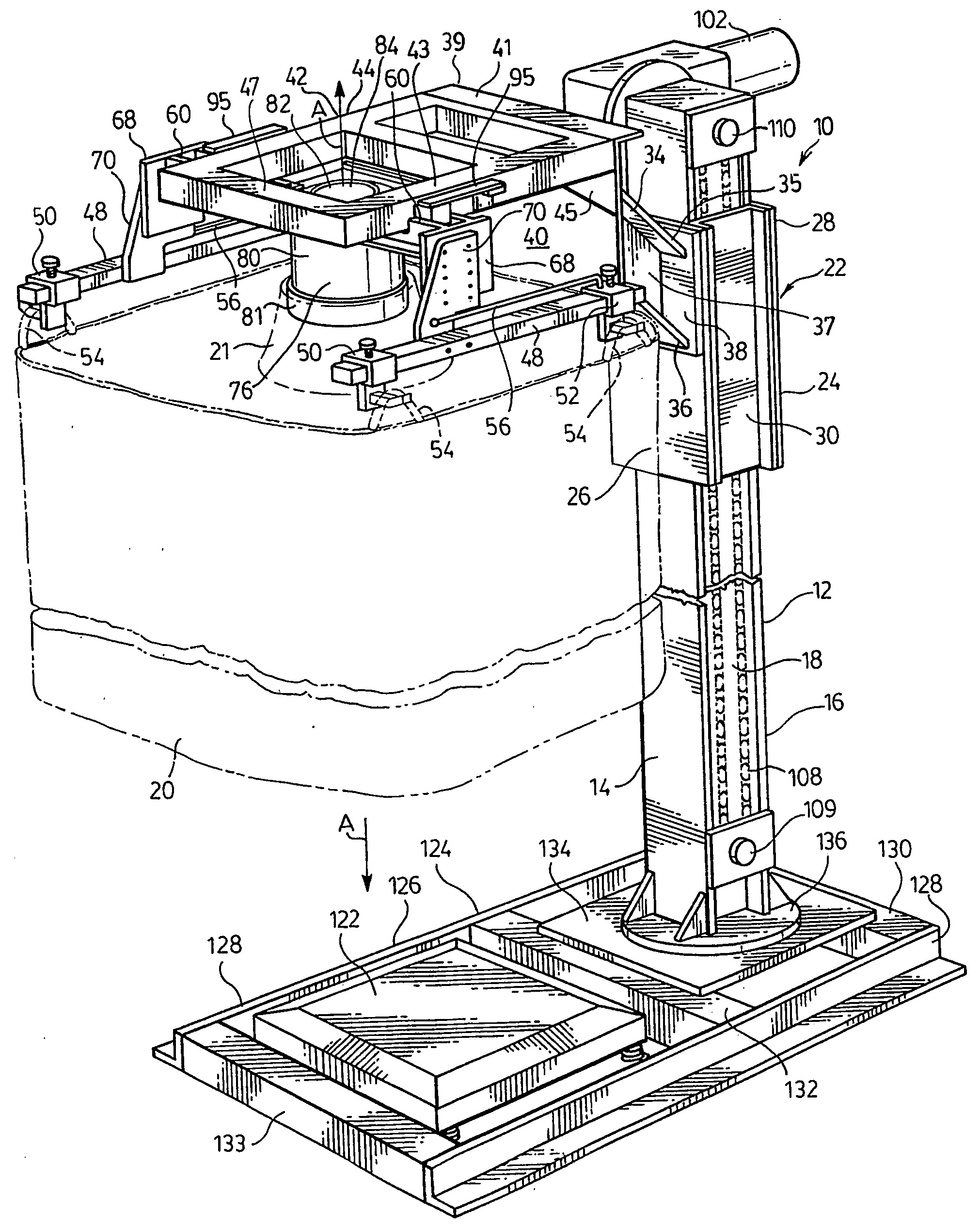
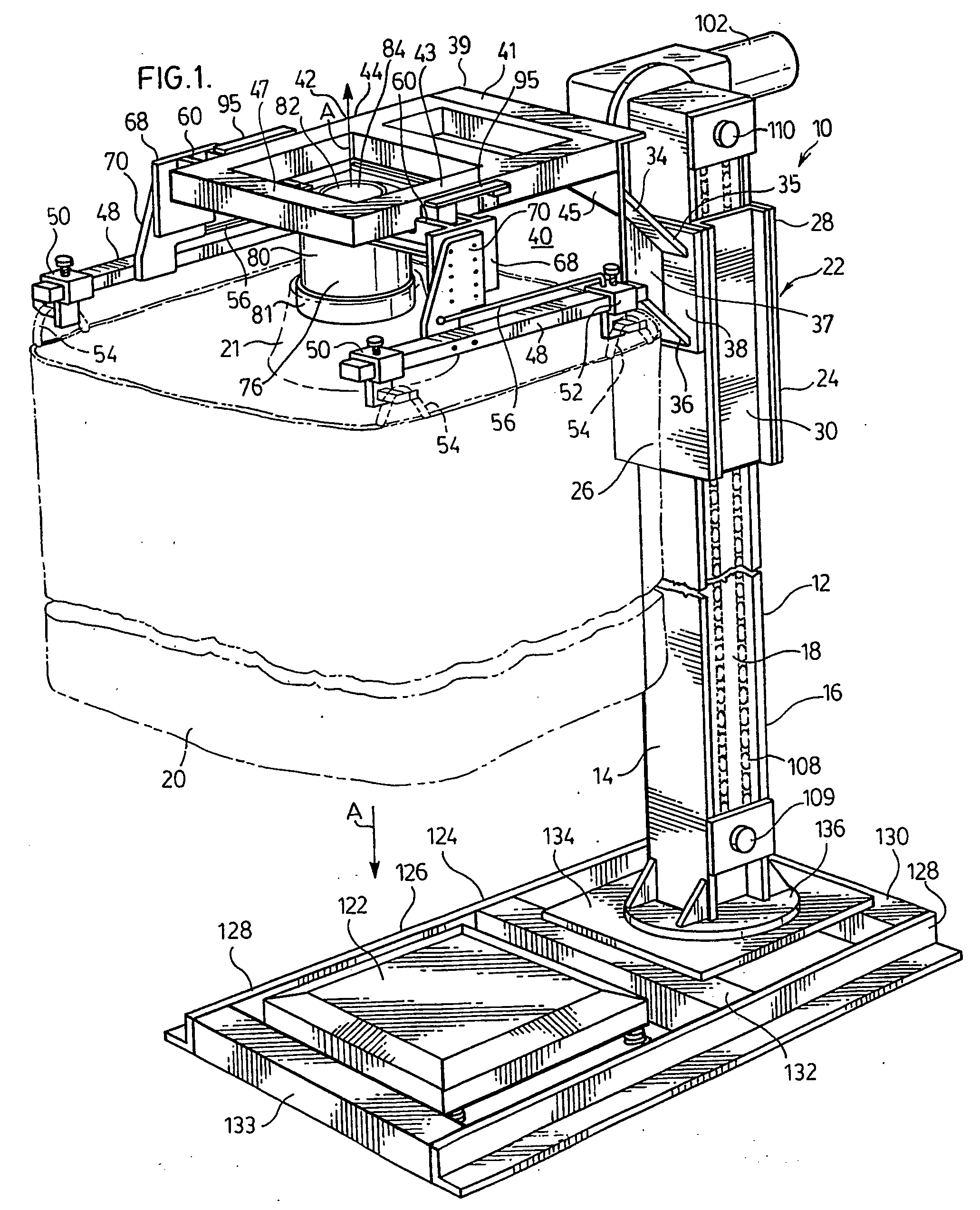
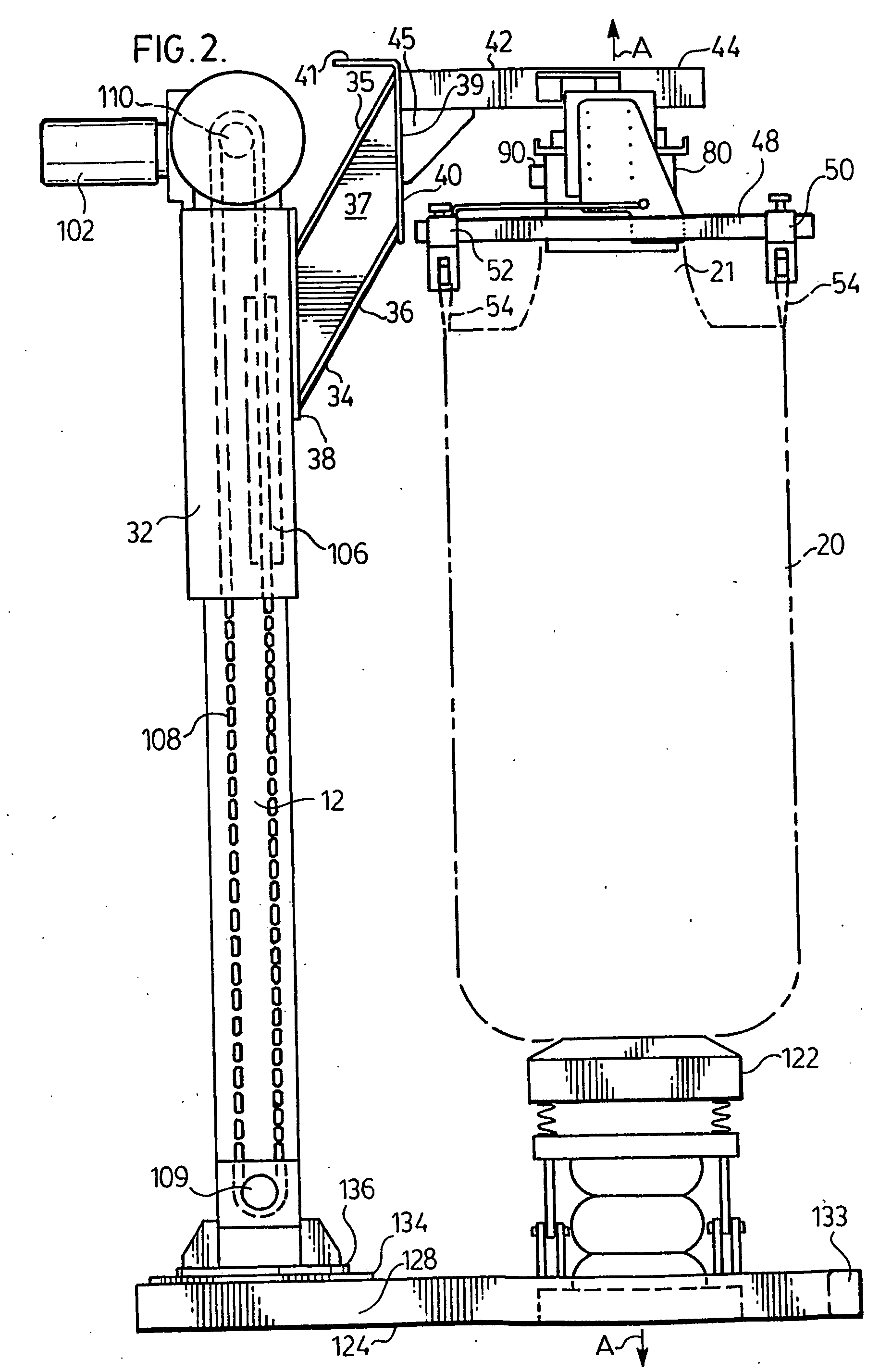
[0054]FIGS. 1 to 4 illustrate a bag filling apparatus 10 for filling a bulk bag 20 according to the invention. Bag filling apparatus 10 comprises a single support post 12 extending vertically from the base to the top of the apparatus 10. The support post 12 preferably comprises a steel I-beam having parallel front and rear flanges 14, 16 connected by a web 18. Although it may be preferred to construct support post 12 from a single I-beam, it will be appreciated that post 12 could be of a different construction. For example, post 12 could be of tubular construction or may comprise two or more vertical members, for example as shown in U.S. Pat. No. 6,564,534 (Poulton et al.).

[0055]Apparatus 10 further comprises a carriage frame 22 from which the bag 20 is suspended. The carriage frame 22 comprises a rectangular sleeve 24 which surrounds the support post 12 and is mounted for reciprocal vertical movement along the support post 12. The rectangular sleeve 24 is shown as comprising a fron...

second embodiment

[0073]An apparatus 150 according to the invention is now described below with reference to FIGS. 5 to 8. Apparatus 150 incorporates many of the same components as in apparatus 10 described above. Accordingly, these components are referred to using the same reference numbers and a detailed description of these components is omitted.

[0074]Apparatus 150 includes a support post 12 (FIG. 6) and a carriage frame 152 which includes a rectangular sleeve 24. The support post 12 and rectangular sleeve 24 of apparatus 150 may preferably be the same as the like-numbered components of apparatus 10 described above. It will be appreciated that apparatus 150 preferably also includes a drive mechanism (not shown) which may be the same as the chain drive mechanism 100 of apparatus 10 described above.

[0075]The carriage frame 152 comprises a support arm 154 projecting forwardly from the front plate 26 of rectangular sleeve 24. The support arm is shown in cross section in FIG. 6. It is preferred that su...

fourth embodiment

[0086]An apparatus 250 according to the invention is now described below with reference to FIGS. 9 to 11. Most of the components of apparatus 250 are similar or identical to the components of apparatus 150 and / or 10 described above, and are referred to with the same reference numerals. Detailed description of these components is omitted.

[0087]The apparatus 250 includes a support post 12 (not shown) which may preferably be the same as the support post 12 of apparatus 10. The apparatus 250 includes a carriage frame 252 having a rectangular sleeve 24 which may preferably be the same as that of apparatus 10 and a support arm 154 which may preferably be identical to that of apparatus 150.

[0088]The apparatus 250 further comprises a filling head 200 which includes an inner cylinder 202, and outer cylinder 204 with a flange 205, an annular flange 206 sealed to the inner cylinder 202, a vacuum fitting 210 (not shown) for evacuating an annular space 208, an annular ring 212 and an inflatable ...


PUM

PropertyMeasurementUnit
angleaaaaaaaaaa
angleaaaaaaaaaa
angleaaaaaaaaaa

Abstract

A bulk bag filling apparatus comprises a first support member having an upper end and a lower end and being oriented in a generally vertical direction; a second support member connected to said generally vertical member and extending at an angle to said generally vertical direction; a filling head for engagement with an opening of the bulk bag, wherein the filling head is connected to and supported by the second support member; a bulk bag support structure for engagement with support elements of the bulk bag, wherein the bulk bag support structure is connected to and supported by the second support member; and a hang-weighing mechanism for weighing the contents of the bulk bag, wherein the bulk bag support structure is connected to said second support member through said hang-weighing mechanism. The hang-weighing apparatus includes one or two load-bearing points at which the bulk bag support structure applies a load to the hang-weighing apparatus. A load cell is preferably provided at each of said load-bearing points, wherein each of said load cells converts said load into an electrical signal representative of the weight of the bulk bag and its contents.

Description

FIELD OF THE INVENTION[0001]The invention relates to an apparatus for filling bulk bags, and specifically to such an apparatus having a simplified, modular construction.BACKGROUND OF THE INVENTION[0002]The filling of bulk bags, also known as flexible intermediate bulk containers or “FIBCs” is typically accomplished by a filling machine having means for hanging the bag and connecting the bag to the nozzle of a discharge apparatus. In addition, the filling machine may be provided with means for weighing the bag as it is being filled, means for raising and lowering the bag, means for vibrating and compacting the contents of the bag during filling, and means for controlling discharge of particulate material into the atmosphere during filling of the bag. Bag filling machines incorporating one or more of these features are disclosed in U.S. Pat. Nos. 6,564,534 (Poulton et al.), 5,336,853 (Davidson) and 4,718,464 (Delves et al.).[0003]One disadvantage of existing bag filling machines is th...

Claims


Application Information

Patent Timeline
Patent Type & Authority Applications(United States)
IPC IPC(8): B65B1/04
CPCB65B1/32G01G19/14G01G15/00
Inventor MACKRILL, DONZANDI-HANJARI, BAHRAM
Owner SPIROFLOW SYST
Why Eureka
Try Eureka