Flange connection

Inactive Publication Date: 2009-12-03
INFICON GMBH
View PDF18 Cites 35 Cited by
  • Summary
  • Abstract
  • Description
  • Claims
  • Application Information

AI Technical Summary

Benefits of technology

[0013]The invention consequently addresses the problem of eliminating the disadvantages of prior art. The present invention in particular addresses the problem of providing a flange connection in which no virtual leaks occur, which cover all previously li

Problems solved by technology

When used in vacuum technology it is undesirable that in these known small flange connections and bolted connections, regions with voids are generated, which release uncontrollably trapped gases and hereby represent sources of virtual leaks.
Such

Method used


Image

  • Flange connection
  • Flange connection
  • Flange connection

Examples


Example

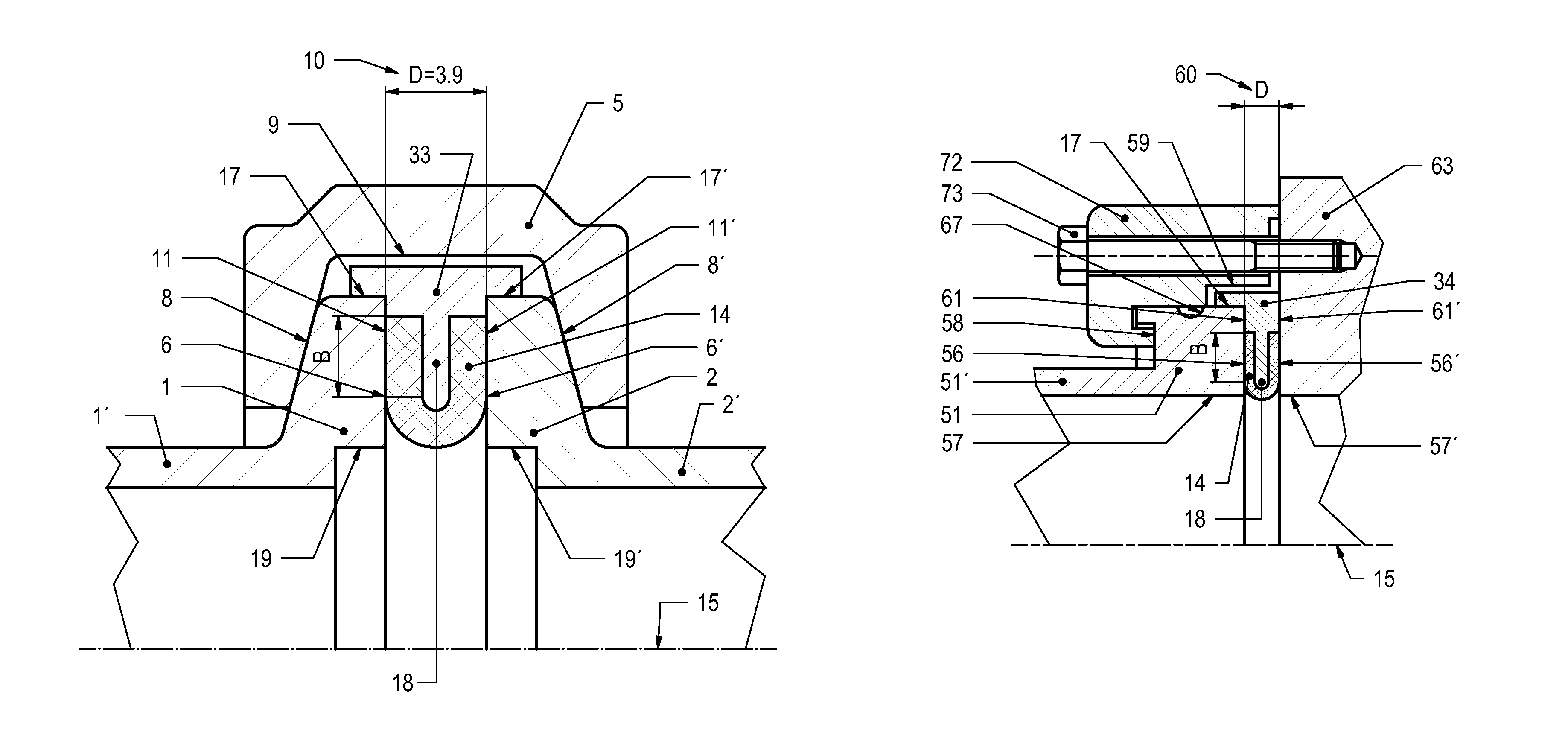
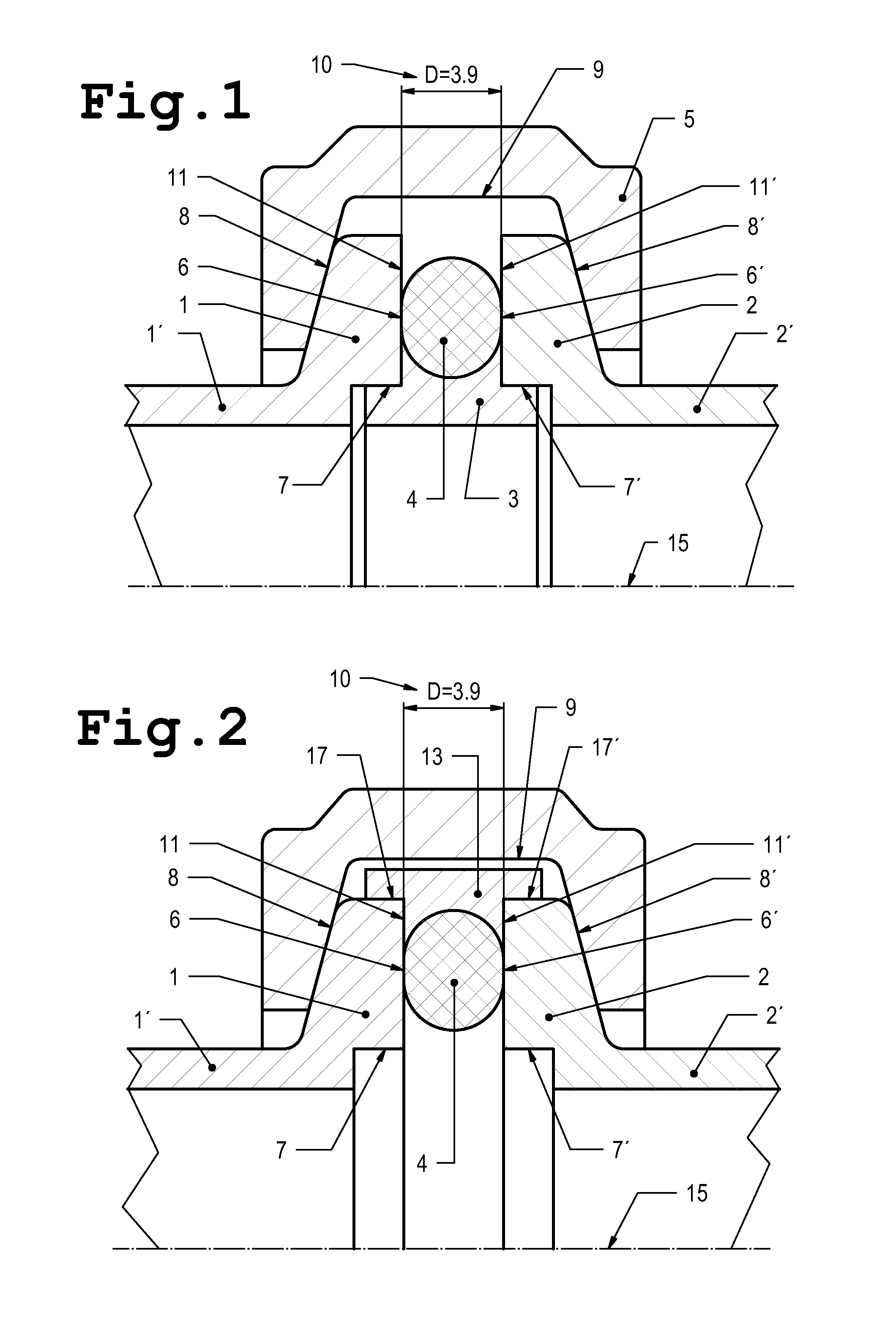
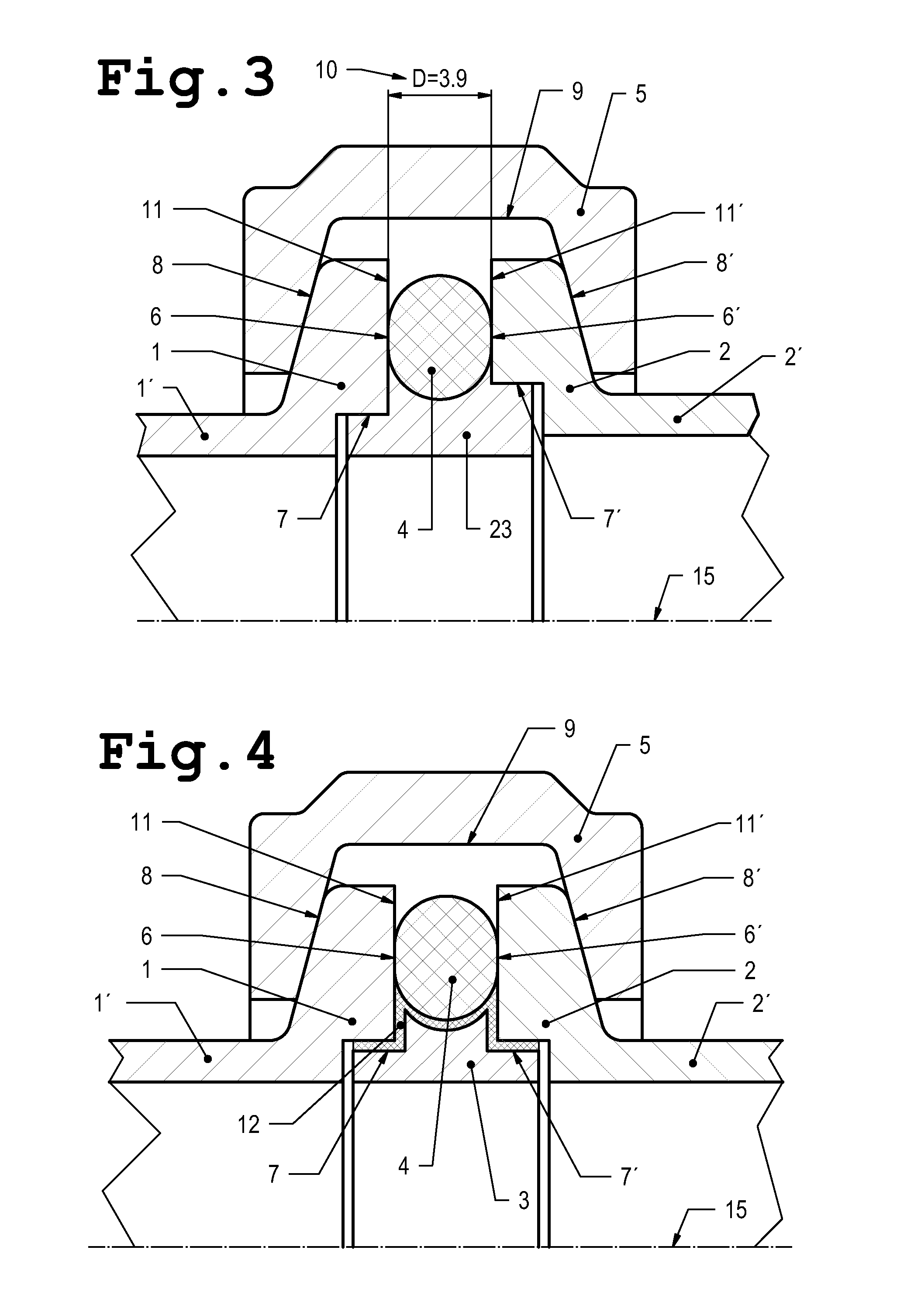
[0035]In the following small flange configurations are depicted and described in FIGS. 1 to 6 and in FIGS. 7 to 15 are depicted bolted flange connections.

[0036]FIG. 1 shows schematically and in cross section the known manner according to prior art of realizing a small flange connection with two like pipe ends 1′, 2′ with pipe axis 15 and flanges 1, 2, disposed thereon. The flanges 1, 2 have in the radial direction one flange face 11, 11′ each which in the assembled state are parallel to one another. Sealing takes place in the following manner: an inner centering ring 3 centers the flanges 1, 2 at the inner located contact faces 7, 7′, which are formed by turned grooves at the pipe ends such that the centering ring 3 is set into these turned grooves. The thickness D of the centering ring defines the flange distance 10 while the two flange faces 11, 11′ are in contact on this ring. An elastomer sealing ring 4, an O-ring seal, encompasses the centering ring 3 and has a greater diameter...


PUM


Abstract

A flange connection has two pipe ends (1′, 2′, 51′, 52′) on each of which one flange (1, 2, 51, 52) is disposed and which have flange faces (11, 11′, 61, 61′) and a centering ring (33, 34) with an elastomer sealing ring (14) in contact with the ring. Both flanges include a mechanism for the detachable clamping against one another such that the flange faces (11, 11′, 61, 61′) are in contact on the centering ring and thereby are held at a predetermined flange distance (10, 60, D). The elastomer sealing ring (14) is pressed on the flange faces (11, 11′, 61, 61′) in the direction of the pipe axes (15) forming a seal, wherein the centering ring (33, 34) is positioned such that it is at least partially in contact on the periphery of the flanges (1, 2, 51, 52). A bearing mechanism (18) is disposed thereon, annularly directed inwardly, about which the elastomer sealing ring (14), which is U-shaped in cross section, is disposed such that on the side flanks of the U-shape, on both sides, an annular areal flange contact zone (6, 6′, 56, 56′, B) is formed.

Description

FIELD AND BACKGROUND OF THE INVENTION[0001]The invention relates to a flange connection.[0002]Elastomer-sealed flange connections for the simple, quick and tight connection of two pipe parts have been known for a long time and in the most diverse types and are utilized in particular in vacuum technology when setting up vacuum systems.[0003]Such elastomer-sealed flange connections are standardized as small flange connections, denoted as ISO-KF flanges, and as bolted flange connections, for example denoted as ISO-K flanges, internationally via PNEUROP (www.pneurop.org) or ISO (www.iso.org) and are applied in the vacuum industry.[0004]The main nominal dimensions in small flange connections are: DN 10 / 16 / 25 / 40 / 50 ISO-KF and the auxiliary nominal dimensions: DN 20 / 32 ISO-KF. The dimensions are defined according to DIN 28403 and also according to ISO 2861 / I. The two pipe ends bear flanges with conical tightening faces onto which acts an annular detachable clamp. Between the flange faces i...

Claims


Application Information

Patent Timeline
IPC IPC(8): F16L23/032F16L55/00
CPCF16L23/18F16L23/036F16J15/061F16J15/127
Inventor KELLER-STAUB, PIERIONOGOOD, PASCAL
Owner INFICON GMBH
Why Eureka
Try Eureka