Nozzle plate for improved post-bonding symmetry

a nozzle plate and post-bonding technology, applied in the field of nozzle plates, can solve problems such as expanding a swath area, and achieve the effect of improving post-bonding symmetry and reducing substantially swath expansion

Active Publication Date: 2009-12-03
SLINGSHOT PRINTING LLC
View PDF22 Cites 17 Cited by
  • Summary
  • Abstract
  • Description
  • Claims
  • Application Information

AI Technical Summary

Benefits of technology

[0015]In another aspect, embodiments of the present invention provide a method for preparing a nozzle plate for bonding to a chip for configuring a printhead of a printing device. The chip comprises a plurality of energizing elements. The nozzle plate includes a plurality of nozzle holes, such that each nozzle hole of the plurality of nozzle holes is capable of being associated with an energizing element of the plurality of energizing elements. The method comprises ablating at least a portion of a wall of each nozzle hole for configuring an asymmetrical flow-feature for the each nozzle hole. The nozzle plate may be disposed on the chip for aligning a central axis of the each nozzle hole at a pre-defined distance from a central axis of the energizing element associated with the each nozzle hole. The asymmetrical flow-feature for each nozzle hole, prior to bonding the nozzle plate to the chip, provides a substantially symmetrical post-bonding process flow-feature.
[0016]The substantially symmetrical flow-feature, i.e., improved post-bonding symmetry, for the each nozzle hole provides the desired directionality to the ink droplets ejected from an opening in the each nozzle hole. In an aspect of the present invention, the at least a portion of the wall of the each nozzle hole may be ablated using laser ablation technique with grayscale mask for configuring the asymmetrical flow-feature for the each nozzle hole. The asymmetrical flow-feature structure of the each nozzle hole in the pre-bonding stage compensates for deformation of a nozzle plate during the bonding of the nozzle plate to the chip and reduces substantially the swath expansion that results from the deformation of the nozzle plate during the bonding process.

Problems solved by technology

Moreover, asymmetrical flow-features may also result in expanding a swath area, i.e., an area traced on the media sheet by the printhead, during a particular unidirectional scan of a printhead onto the media sheet.

Method used


Image

  • Nozzle plate for improved post-bonding symmetry
  • Nozzle plate for improved post-bonding symmetry
  • Nozzle plate for improved post-bonding symmetry

Examples


Embodiment Construction

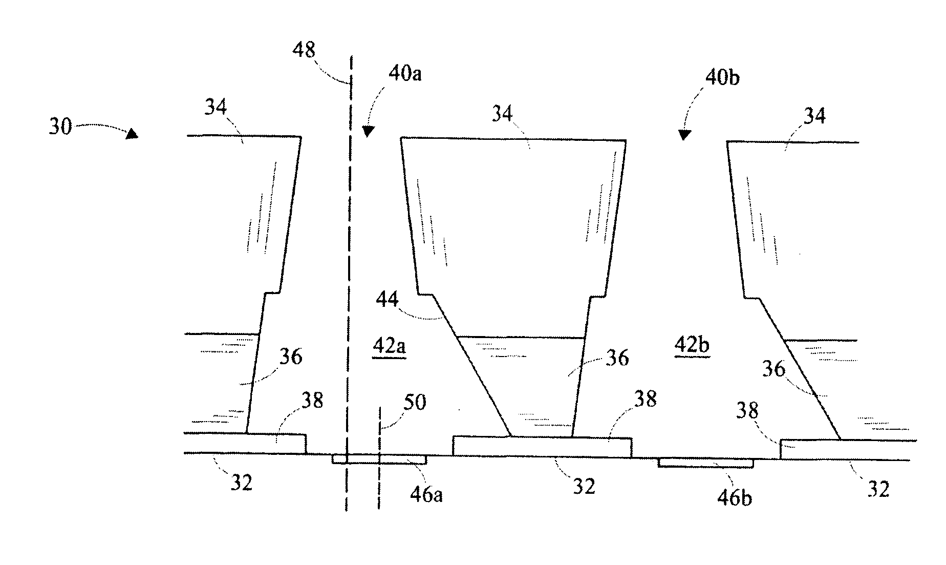
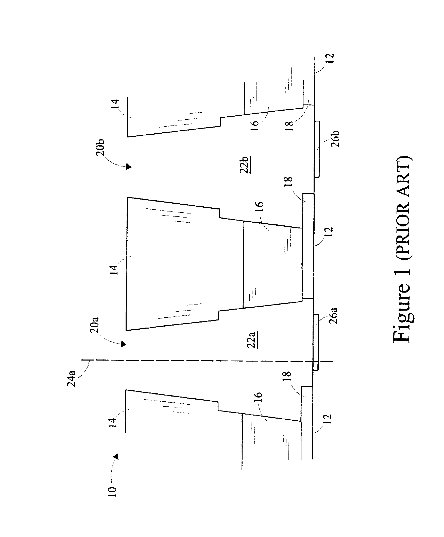
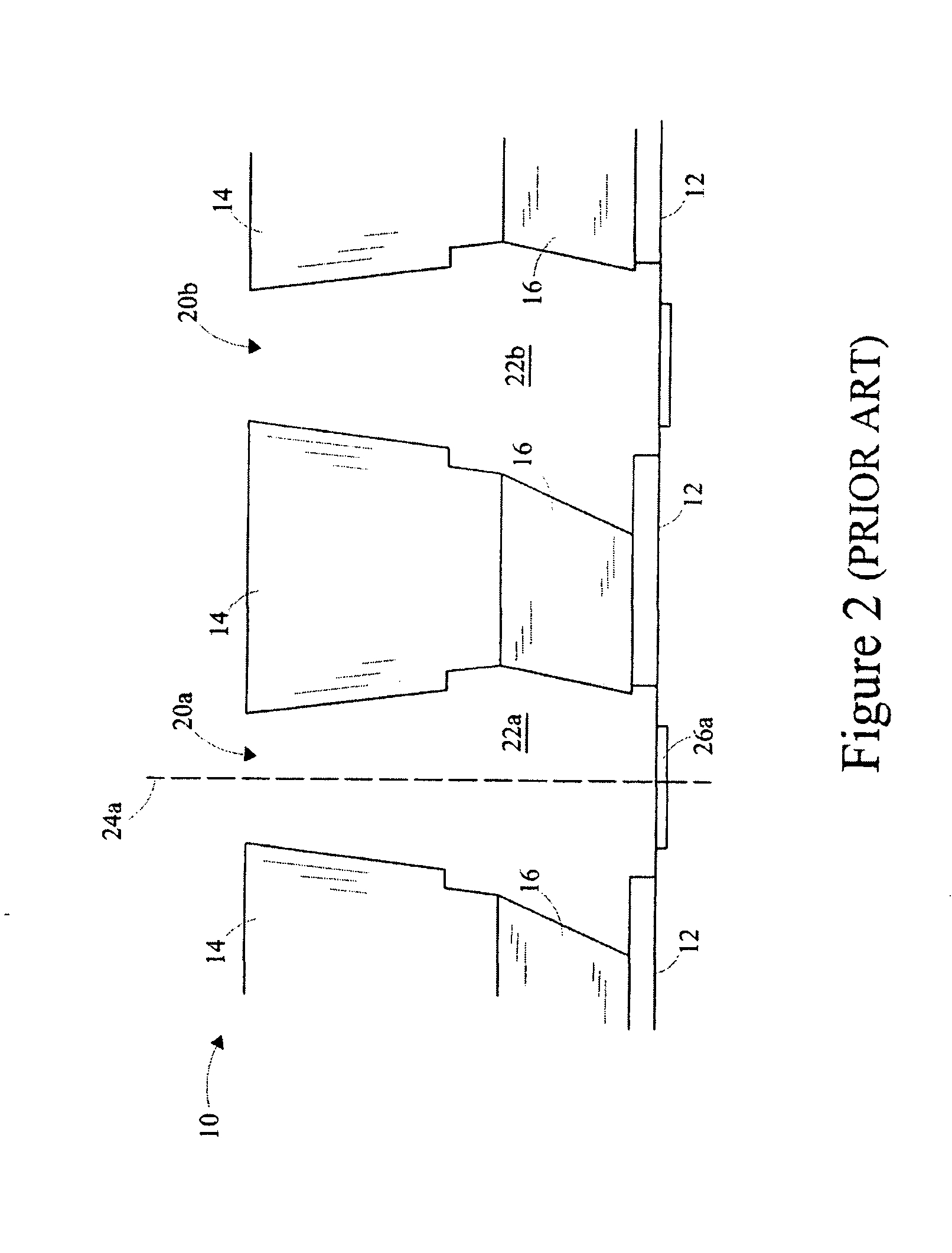
[0023]It is to be understood that the present invention is not limited in its application to the details of construction and the arrangement of components set forth in the following description or illustrated in the drawings. The present invention is capable of other embodiments and of being practiced or of being carried out in various ways. Also, it is to be understood that the phraseology and terminology used herein is for the purpose of description and should not be regarded as limiting. The use of “including,”“comprising,” Or “having” and variations thereof herein is meant to encompass the items listed thereafter and equivalents thereof as well as additional items.

[0024]In addition, it should be understood that embodiments of the present invention include both hardware and electronic components or modules that, for purposes of discussion, may be illustrated and described as if the majority of the components were implemented solely in hardware. However, one of ordinary skill in t...


PUM


Abstract

A nozzle plate for bonding to a chip for configuring a printhead of a printing device is disclosed. The chip comprises a plurality of energizing elements. The nozzle plate comprises a substrate layer, an adhesive layer and a plurality of nozzle holes perforated in the substrate layer and the adhesive layer. The each nozzle hole is capable of being associated with an energizing element of the plurality of energizing elements. The each nozzle hole comprises an asymmetric flow-feature configured by ablating at least a portion of a wall of the each nozzle hole prior to bonding the nozzle plate to the chip. The nozzle plate provides a substantially symmetrical flow-feature for the each nozzle hole on bonding to the chip.

Description

BACKGROUND[0001]1. Field of the Invention[0002]The invention relates generally to printheads in printing devices, and, more particularly, to a nozzle plate for bonding to a chip for configuring a printhead of a printing device.[0003]2. Description of the Related Art[0004]Printing devices commonly referred to as printers, are widely used in offices, in homes and in business enterprises. The printing devices output information displayed on a screen of a data processing device onto a media sheet such as a sheet of paper. The information may be output onto the media sheet by impacting desired information elements, such as characters, onto the media sheet, or alternatively, the printing devices may propel droplets of liquid medium, such as ink, onto the media sheet for outputting the information onto the media sheet. Commonly used printing devices, such as inkjet printers, propel ink droplets onto the media sheet for transferring the information onto the media sheet. The inkjet printers ...

Claims


Application Information

Patent Timeline
Patent Type & Authority Applications(United States)
IPC IPC(8): B41J2/14
CPCB41J2/1433B41J2/162B41J2202/11B41J2/1634B41J2/1623
Inventor GOIN, RICHARD LOUISLINGLE, CHRISTOPHER ELLIOT
Owner SLINGSHOT PRINTING LLC
Why Eureka
Try Eureka