Measurement based voltage stability monitoring and control

a voltage stability monitoring and control system technology, applied in process and machine control, instruments, nuclear elements, etc., can solve the problems of incompetence to monitor and control voltage stability at load centers, high proportional amount of load demand provided, and high risk of voltage instability in load centers

Active Publication Date: 2009-12-03
ELECTRIC POWER RES INST INC
View PDF3 Cites 22 Cited by
  • Summary
  • Abstract
  • Description
  • Claims
  • Application Information

AI Technical Summary

Benefits of technology

[0006]These and other shortcomings of the prior art are addressed by the present invention, which provides a measurement based voltage stability monitoring and control (MBVSMC) scheme for monitoring and controlling voltage stability at load centers.
[0007]According to one aspect of the present invention, a voltage stability monitoring scheme includes a means for measuring current or voltage phasors at a boundary bus of a load center; an equivalent network having a fictitious bus with an aggregate load representative of all loads of the load center; and a computing device to calculate a voltage stability margin index based on the aggregate load of the fictitious bus and compare the voltage stability margin index to a pre-set threshold. The computing device causes an action to take place based on the comparison between the voltage stability margin index and the pre-set threshold.
[0008]According to one aspect of the present invention, a method of controlling voltage stability at load center includes the steps of measuring current and voltage phasors at a boundary bus of a load center; determining a maximum power transfer from an external system to the load center; and determining a voltage stability margin in

Problems solved by technology

Because there are few local power plants to satisfy the demand, the load center is usually supplied by multiple transmission sources through a number of boundary buses, resulting in a high proportional amount of load demand being provided by external power systems and heavy power flow on the interface transmission line

Method used


Image

  • Measurement based voltage stability monitoring and control
  • Measurement based voltage stability monitoring and control
  • Measurement based voltage stability monitoring and control

Examples


Embodiment Construction

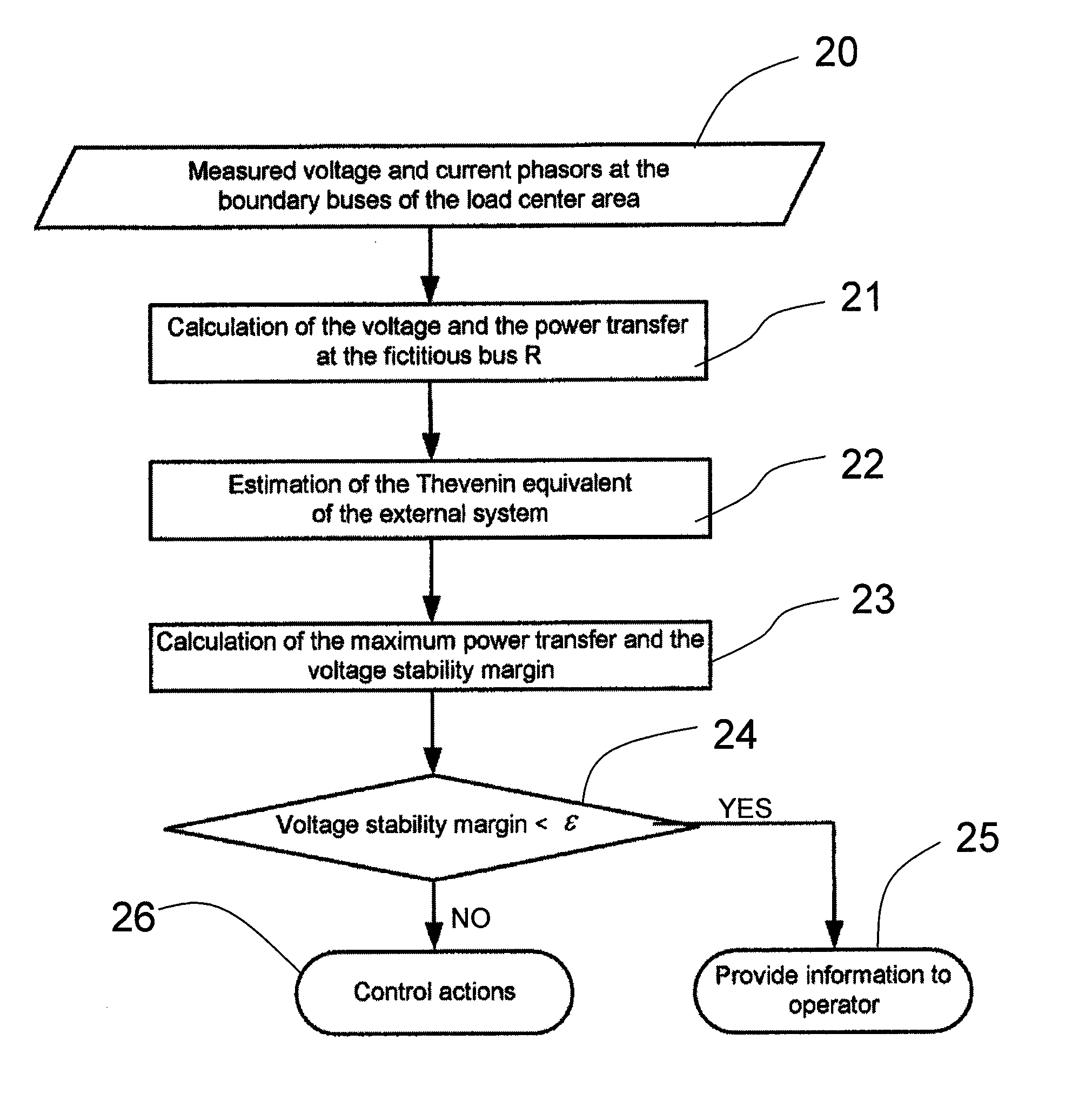
[0015]Referring to the drawings, an exemplary measurement based voltage stability monitoring and control (MBVSMC) scheme and method according to the present invention is illustrated in FIGS. 1-4.

[0016]The MBVSMC scheme calculates an index referred to as “Voltage Stability Margin” (VSM) index to continuously monitor and track the voltage stability condition at load centers. The VSM index may be expressed in terms of active, reactive, and apparent power, and may be used as an adaptive triggering criterion for further control actions.

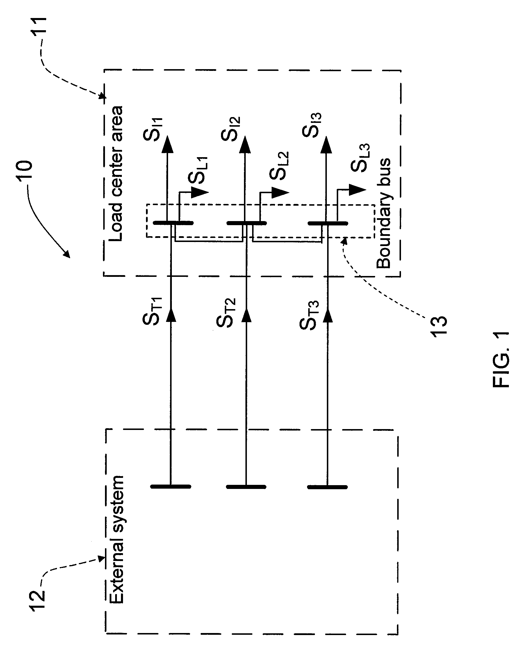
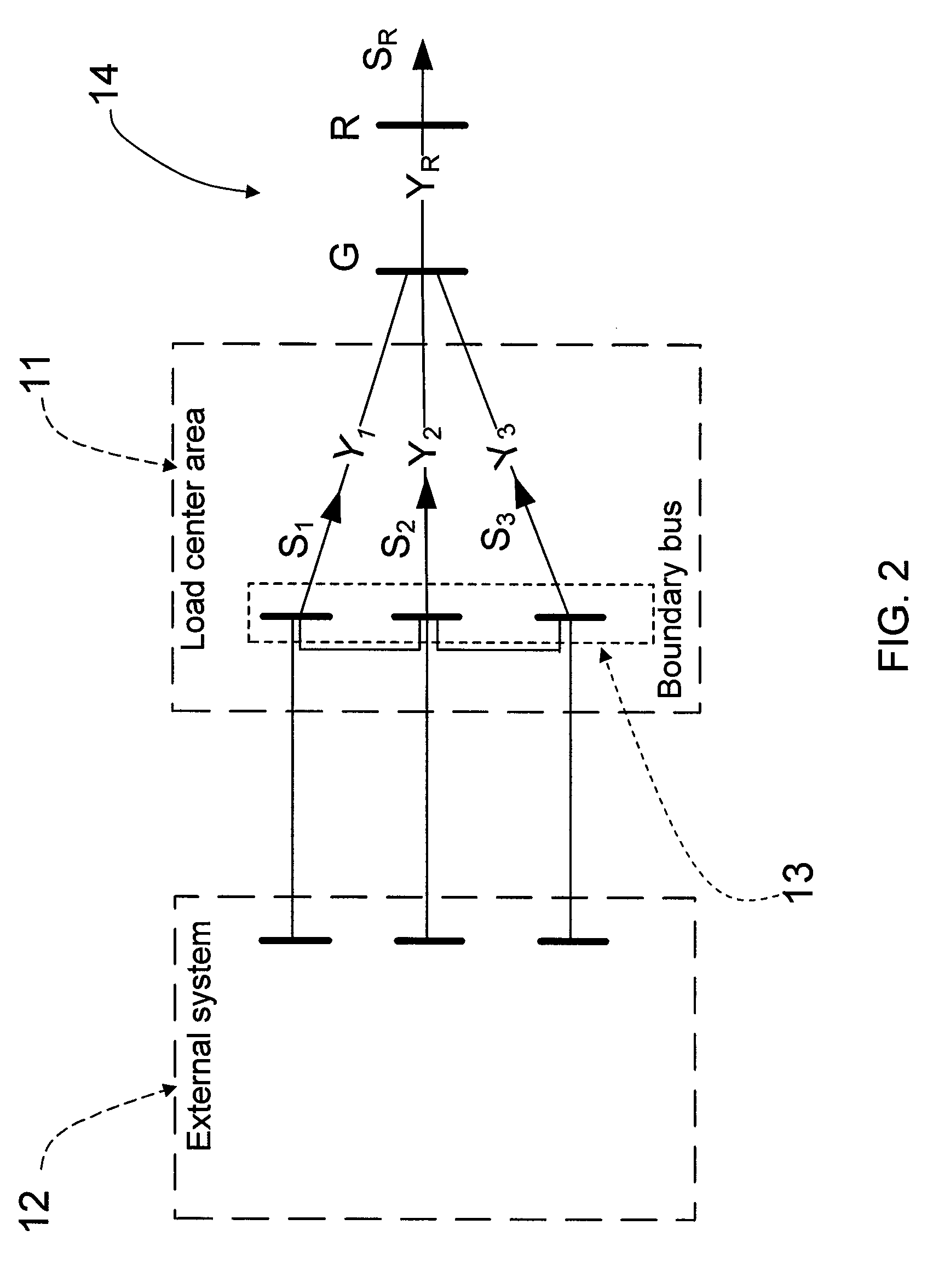
[0017]The MBVSMC provides a means (such as a computer, volt and current meters, and any other suitable equipment or method) for measuring current and voltage phasors at boundary buses of a load center area by using an equivalent method to aggregate a total load of the load center area to a fictitious bus and estimating a Thevenin equivalent to represent the external power system. The MBVSMC then calculates the VSM index and compares the VSM with a pre-set ...


PUM


Abstract

A measurement base voltage stability monitoring and control scheme having a means for measuring current and voltage phasors at a boundary bus of a load center; and an equivalent network having a fictitious bus with an aggregate load representative of all loads of the load center. The scheme further includes a computing device to calculate a voltage stability margin index based on the aggregate load of the fictitious bus and compare the voltage stability margin index to a pre-set threshold. The computing device causes an action to take place based on the comparison between the voltage stability margin index and the pre-set threshold.

Description

BACKGROUND OF THE INVENTION[0001]The present invention relates generally to a voltage stability monitoring and control system / scheme, and more particularly to a system and a method for determining voltage stability margin at load centers to enhance power system voltage stability monitoring and control capability.[0002]A load center is generally defined as a particular geographical area where load demand is high and has few local power plants to satisfy the local power demand. Because there are few local power plants to satisfy the demand, the load center is usually supplied by multiple transmission sources through a number of boundary buses, resulting in a high proportional amount of load demand being provided by external power systems and heavy power flow on the interface transmission lines.[0003]Because of these properties, load centers are more susceptible to voltage instability and are typically voltage weak areas. Therefore, monitoring voltage stability at load centers is impor...

Claims


Application Information

Patent Timeline
IPC IPC(8): G01R27/00
CPCH02J3/14G05F1/70Y04S20/222Y02B70/3225H02J2310/60
Inventor ZHANG, PEIMIN, LIANGCHEN, JIAN
Owner ELECTRIC POWER RES INST INC
Why Eureka
Try Eureka