Systems and methods for triggering and cycling a ventilator based on reconstructed patient effort signal

a technology of effort signal and ventilator, applied in the field of ventilator, can solve the problems of insufficient accuracy of approaches, limited operation of ventilation system, and difficulty in identifying respiratory parameters

Active Publication Date: 2009-12-10
TYCO HEALTHCARE GRP LP
View PDF104 Cites 159 Cited by
  • Summary
  • Abstract
  • Description
  • Claims
  • Application Information

AI Technical Summary

Problems solved by technology

In many cases, proper operation of a ventilation system is limited by the accuracy at which such parameters are defined or estimated.
Historically, identifying respiratory parameters posed a challenge in the case of the ventilation system driven by unknown input signals.
This is the case with the ventilation systems involving actively breathing patients and leaks, and many existing approaches fail to provide sufficiently accurate results because these signals driving the system typically cannot be measured but they must be accounted for in the identification algorithms.
For example, various approaches for estimating patient breathing effort are inaccurate, and as such dynamic methods relying on an estimated patient effort are often inadequate.
The reliability of such an approach is limited by the accuracy at which gas flow in and out of the patient's lungs may be measured.
Such a measurement, however, is inherently inaccurate as it relies on a flow sensor at or near a tube inserted in the patient's trachea.
Further, such a flow sensor near the patient's trachea is often not available in existing ventilation systems.

Method used


Image

  • Systems and methods for triggering and cycling a ventilator based on reconstructed patient effort signal
  • Systems and methods for triggering and cycling a ventilator based on reconstructed patient effort signal
  • Systems and methods for triggering and cycling a ventilator based on reconstructed patient effort signal

Examples


Embodiment Construction

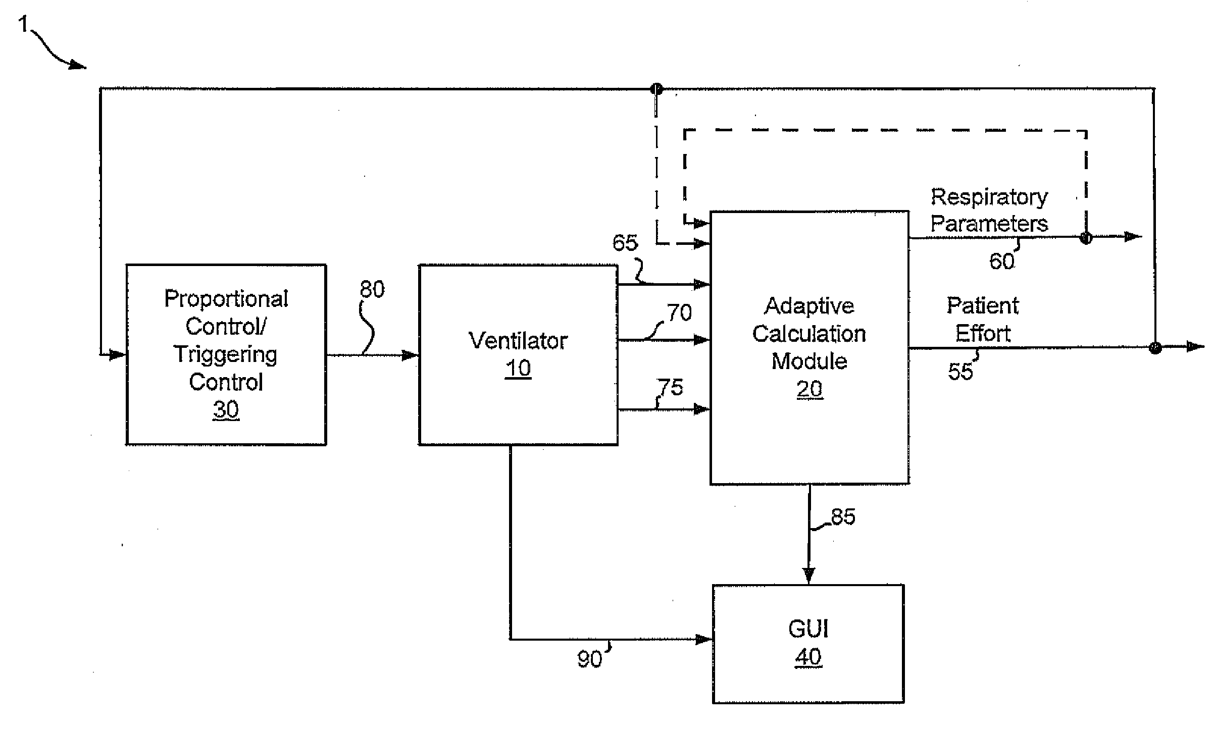
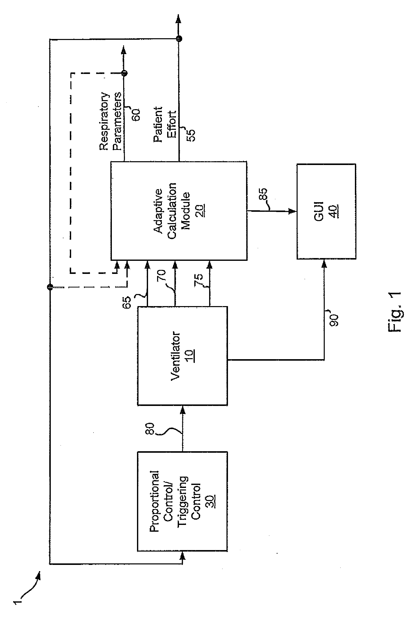
[0029]The present disclosure is related to ventilators, and more particularly to systems and methods for controlling the delivery of gas based on a patient's effort to breathe.

[0030]It is desirable to synchronize the onset and end of a ventilation cycle to effort a patient may be making to breathe on their own (i.e., patient effort). For example, it is desirable to have an accurate ventilator trigger, whereby the ventilator initiates a breath as soon as the patient attempts to inhale. Some ventilators use a pressure trigger which senses a change in ventilation circuit pressure caused by the patient attempting to inhale, while other ventilators use a flow trigger which senses a change in flow caused by the patient attempting to inhale. In either case, delays between the patient's effort and the ventilator response can occur due to a variety of reasons. For example, a leak in the ventilation circuit may allow air to enter the circuit when the patient inhales. Since the entirety of the...


PUM


Abstract

Various embodiments of the present disclosure provide systems, methods and devices for respiratory support. As one example, a method for respiratory support is described that includes providing a measured pressure, and calculating a net flow based on at least one measured inlet flow and measured outlet flow. A relationship between a first value related to the measured pressure, a second value related to the measured net flow and a third value related to patient effort is used to provide a prediction of patient effort. An interim value is updated based at least in part on the prediction of the patient effort, and used to help compute a patient effort. A ventilation cycle is initiated using the computed patient effort.

Description

RELATED APPLICATIONS[0001]This application claims the benefit of U.S. Provisional Application No. 61 / 059,599, filed Jun. 6, 2008, titled “Systems and Methods for Determining Patient Effort and / or Respiratory Parameters in a Ventilation System,” the benefit of U.S. Provisional Application No. 61 / 101,575, filed Sep. 30, 2008, titled “Systems and Methods for Monitoring and Displaying Respiratory Information,” and the benefit of U.S. Provisional Application No. 61 / 101,578, filed Sep. 30, 2008, also titled “Systems and Methods for Monitoring and Displaying Respiratory Information,” and whereby the complete disclosure of each such application is hereby incorporated by reference.BACKGROUND[0002]The present invention is related to ventilators, and more particularly to systems and methods for identification of time dependent signals and / or respiratory parameters in a dynamic ventilation system.[0003]Ventilators are designed to ventilate a patient's lungs with gas, and to thereby assist the p...

Claims


Application Information

Patent Timeline
Patent Type & Authority Applications(United States)
IPC IPC(8): A61M16/00
CPCA61B5/08A61M16/12A61M2016/0015A61M2016/0027A61M2016/0039A61M2016/0036G01F1/00G01F1/34A61M16/0057A61M16/0875A61M16/0003A61M2016/0042A61M16/026A61M16/0051A61M2016/0018A61M2205/3303A61M2205/50
Inventor MASIC, MILENKO
Owner TYCO HEALTHCARE GRP LP
Why Eureka
Try Eureka