Massage assembly

a technology of massaging and assembly, which is applied in the field of massaging assembly, can solve the problems of only providing one single and fixed massage feature of the massaging assembly, and achieve the effect of compact structure and reliabl

Inactive Publication Date: 2009-12-10
TSAI MING WEI
View PDF5 Cites 16 Cited by
  • Summary
  • Abstract
  • Description
  • Claims
  • Application Information

AI Technical Summary

Benefits of technology

[0018]6. The actions of the massage members are continuous and the structure is compact and reliable.

Problems solved by technology

The conventional massage assembly can only provide one single and fixed massage feature.

Method used


Image

  • Massage assembly
  • Massage assembly
  • Massage assembly

Examples


Embodiment Construction

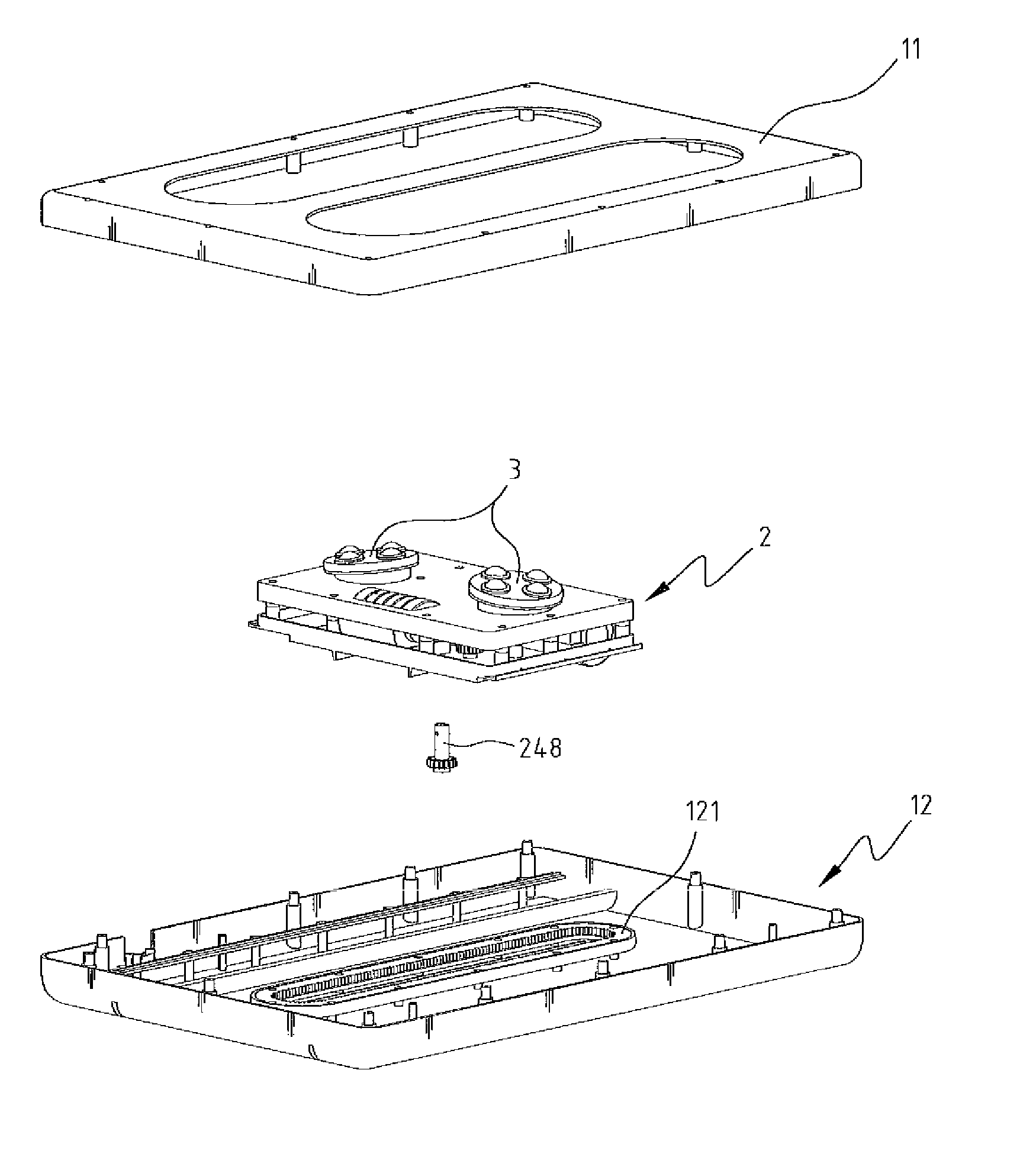
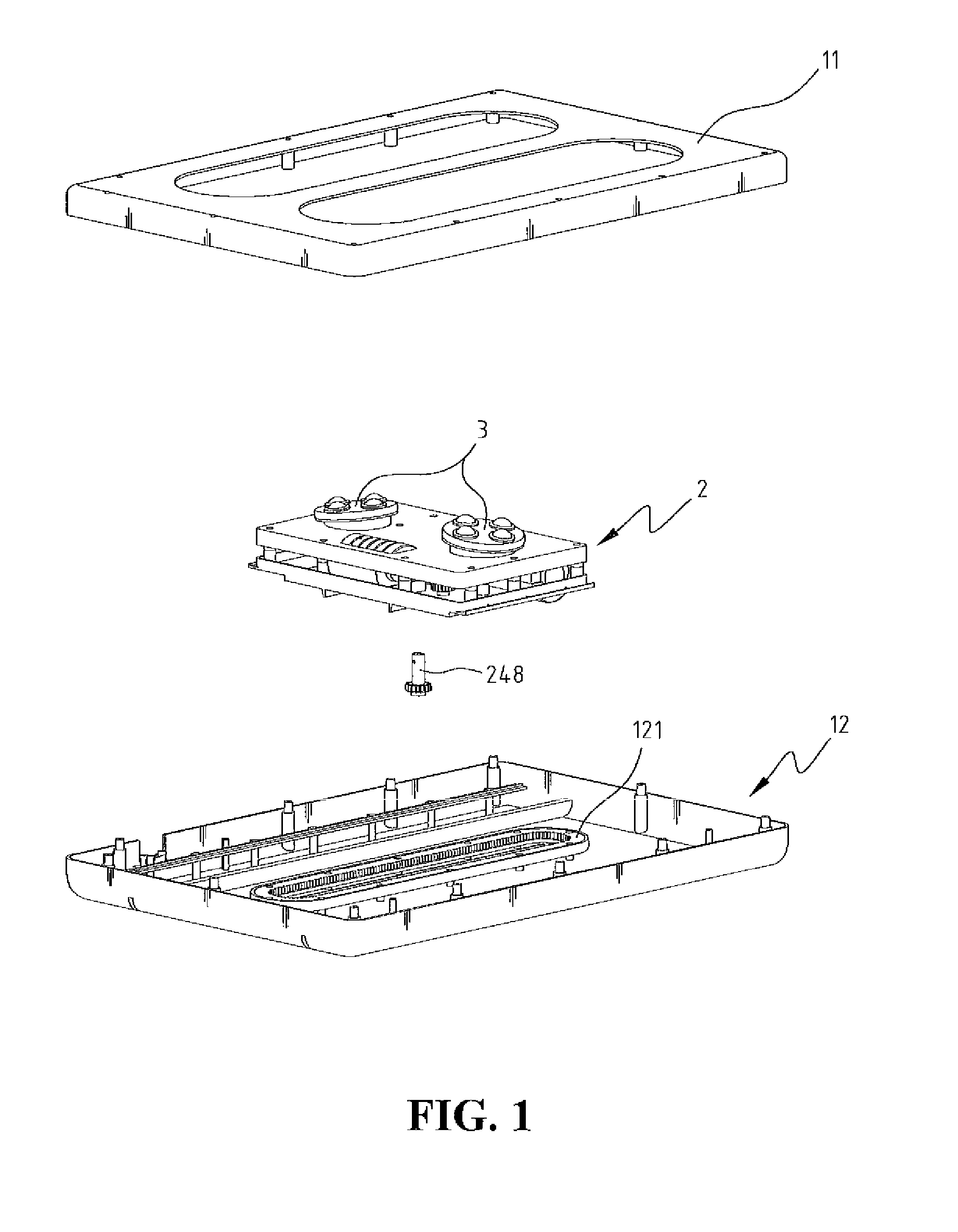
[0029]With reference to the drawings and in particular to FIG. 1, a massage assembly in accordance with the present invention comprises a top cover 11, a base 12 which is connected to the top cover 11 so as to define a space therebetween, a movable unit 2 and a massage unit 3.

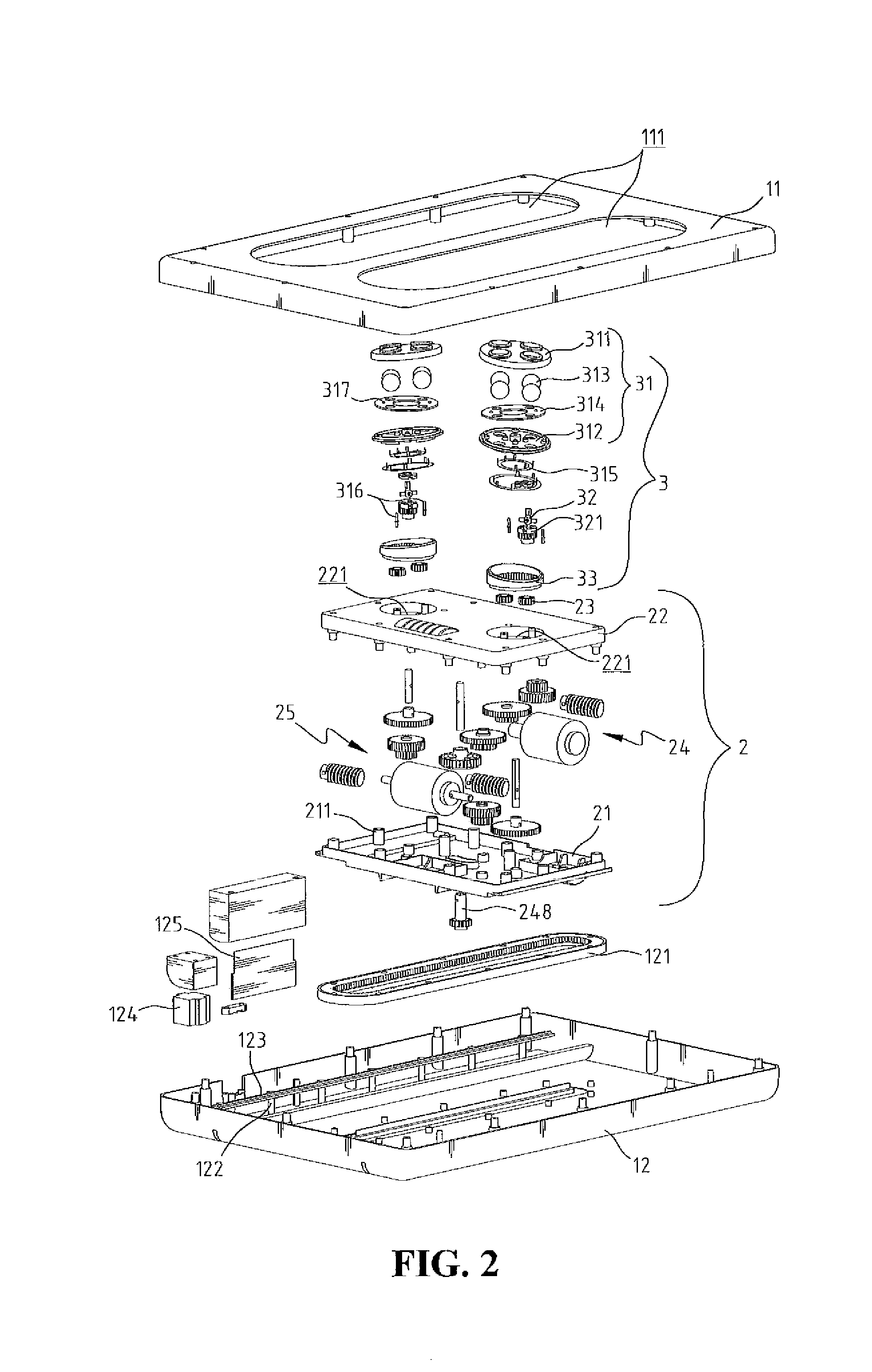
[0030]As shown in FIG. 2, the base 12 has a loop rail 121 located at a center thereof and the loop rail 121 is a closed and elongate loop which has two straight sides with two curved portions and teeth defined in its inside as shown in FIG. 2A. The shape of the loop rail 121 can also be non-uniform such as the left loop rail shown in FIG. 2A. Two rows of rods 122 are located on two sides of the loop rail 121 and two straight rails 123 are connected along the rods 122. The two straight rails 123 are parallel to each other. The base 12 may accommodate adapter, circuit board 125 and wires which are electrically connected to the movable unit 2 and the massage unit 3. The top cover 11 has two openings 111 through wh...


PUM


Abstract

A massage assembly includes a top cover and a base which is connected to the top cover to define a space therebetween, a massage unit and a movable unit is received in the space. The massage unit is connected to the movable unit, and a transmission mechanism is received in the movable unit to drive the movable unit to move reciprocally in the massage assembly so as to massage the user's body by the massage unit. The massage unit provides different types of massage features.

Description

BACKGROUND OF THE INVENTION[0001]1. Field of the Invention[0002]The present invention relates generally to a massage assembly using worm shafts to drive worm gears so as to obtain multiple types of massage features.[0003]2. The Prior Arts[0004]A conventional massage assembly generally includes two massage parts which are movable along two circular tracks. Two worm shafts are used to drive two worm gears which are moved relative to each other and each worm gear has a massage member connected eccentrically thereon so as to massage the user's body. The conventional massage assembly can only provide one single and fixed massage feature.SUMMARY OF THE INVENTION[0005]A primary objective of the present invention is to provide a massage assembly which is designed to improve the shortcomings of the conventional massage assemblies and uses a mechanism which includes worm shafts to drive worm gears so as to provide different types of massage features.[0006]Another objective of the present inve...

Claims


Application Information

Patent Timeline
Patent Type & Authority Applications(United States)
IPC IPC(8): A61H15/00A61H7/00
CPCA61H7/001A61H2015/0064A61H2201/1669A61H2201/1284A61H2201/0149A61H7/007
Inventor TSAI, MING-WEI
Owner TSAI MING WEI
Why Eureka
Try Eureka