Shoulder surgery attachment for a surgical table

a technology for surgical tables and shoulder pads, applied in the field of surgical pads, can solve the problems of insufficient head, neck and torso support, inconvenient cleaning, and inconvenient cleaning

Active Publication Date: 2009-12-17
ORTHOPEDIC POSITIONING SOLUTIONS LLC +1
View PDF15 Cites 29 Cited by
  • Summary
  • Abstract
  • Description
  • Claims
  • Application Information

AI Technical Summary

Benefits of technology

[0007]The headrest assembly is also adjustably moveable in a direction transverse to the upright extension of the chair back assembly. This permits proper engagement of the patient's neck in alignment with the back support.
[0008]The chair back assembly further includes side retainers that adjustably protrude in a forward direction on opposite sides. They are positioned for retaining and confining the sides of the patient's torso. A torso retainer is also preferably provided between these side retainers for retaining a patient's torso against the back support to assist in preventing the patient from sliding down the chair back assembly.
[0009]The forehead clamp includes at least one clamp pad for soft engagement of the patient's forehead. In addition, a contoured back rest support cushion is provided and positioned to freely slide against the chair back. This permits the back rest support cushion to “float” and thereby find the proper position. A knee lift support is also provided on the surgical table and positioned under the patient's knees.

Problems solved by technology

There are, however, problems with current surgical beach-chairs which include inadequate head, neck and torso support, ease of cleanliness and improper sizing.

Method used


Image

  • Shoulder surgery attachment for a surgical table
  • Shoulder surgery attachment for a surgical table
  • Shoulder surgery attachment for a surgical table

Examples


Embodiment Construction

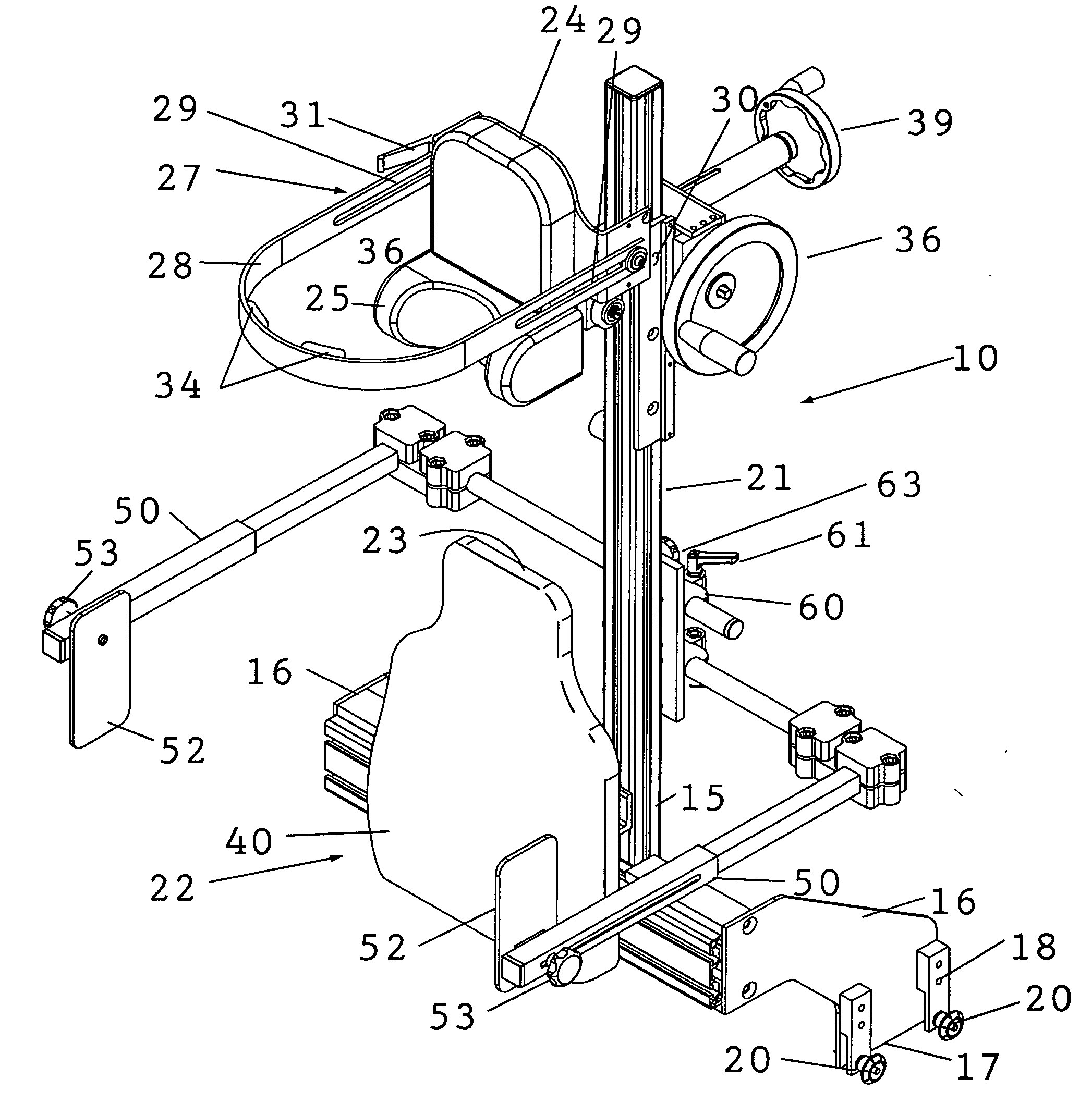
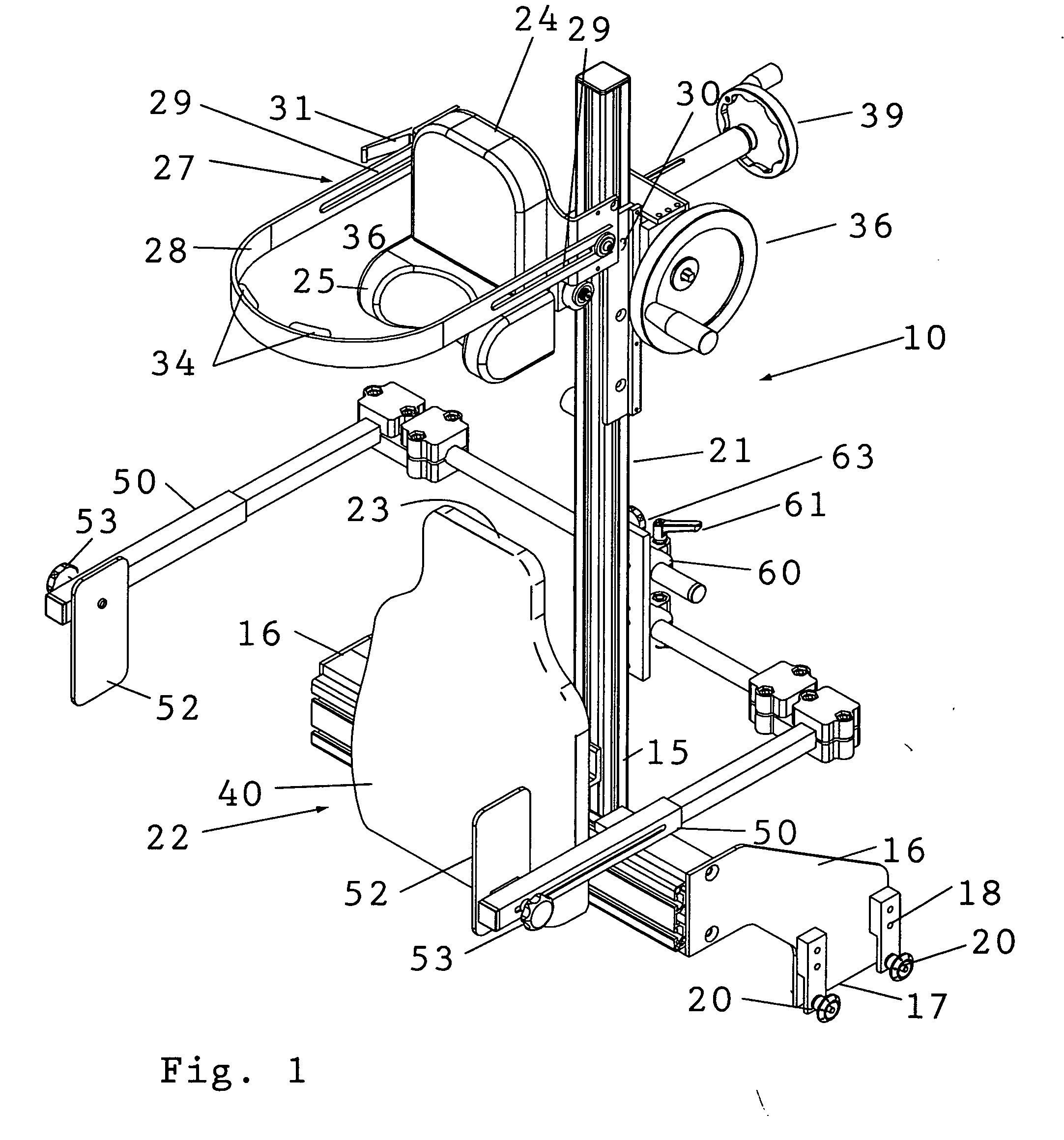
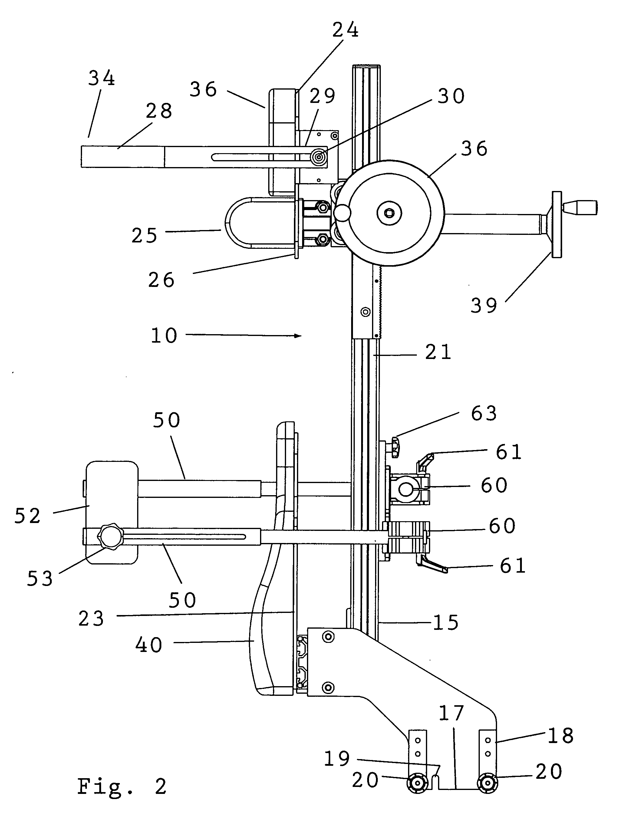
[0018]Referring to the drawings, the shoulder surgery attachment 10 of the present invention is provided for attachment to a common place surgery table 11 (FIG. 7) having an articulated leg section 12 with accessory attachment rails 13 on opposite sides thereof. The accessory attachment rails 13 are spaced from the sides of the articulated leg section 12 by means of periodically spaced standoff support pins 14. The details of such a typical surgical table are illustrated in U.S. Pat. No. 6,564,406, issued to Van Steenburg et al., and accordingly the disclosure therein is incorporated herein by reference for a full understanding of the surgical table construction. The attachment 10 may also be secured to accessory attachment rails on the surgery table 11 itself.

[0019]The shoulder surgery attachment 10 is provided at the base 15 thereof with spaced mount blades 16, that in turn are provided at their distal ends 17 with a rail clamp securement assembly 18. The assemblies 18 are provide...


PUM


Abstract

A shoulder surgery attachment for a surgical table having an articulated leg section with accessory attachment rails on opposite sides. An upright chair back assembly is supported at its base or bottom end thereof for attachment to the accessory attachment rails and the chair back assembly includes a headrest assembly positioned above a back support. The headrest assembly includes a removable neck support and a head fixation assembly. The headrest assembly is adjustably moveable up and down the chair back assembly. The neck support is positioned below the head fixation assembly and protrudes from the front of the headrest assembly for engagement with the back of the patient's neck. The head fixation assembly includes a forward protruding U-shaped forehead clamp having two distal rearwardly extending free ends that are adjustably secured to the headrest assembly whereby the head clamp may be adjusted for engaging the forehead of the patient to clamp the patient's head against the headrest assembly.

Description

RELATED APPLICATIONS[0001]This application is based upon U.S. Provisional Application Ser. No. 61 / 131,992, filed on Jun. 13, 2008, the complete disclosures of which are hereby expressly incorporated herein by this reference thereto.BACKGROUND OF THE INVENTION[0002]The present invention relates to surgical attachments for positioning a patient for surgical procedures and particularly to a shoulder surgery attachment for a surgical table.[0003]Surgical procedures on the shoulders of patients are often preformed with the patients in the so called beach-chair position. In the beach-chair position, a patient is positioned in a sitting position during surgery, although the patient may be anesthetized in a supine line position.[0004]There are presently a number of devices used for positioning patients in the beach-chair position as an accessory for common place surgical tables. As examples, refer to U.S. Pat. No. 5,661,859, issued to Schaefer, U.S. Pat. No. 6,564,406, issued to Van Steenbu...

Claims


Application Information

Patent Timeline
Patent Type & Authority Applications(United States)
IPC IPC(8): A61G7/07A61G7/00
CPCA61G13/12A61G13/121A61G13/122A61G13/1225A61G2200/54A61G13/1245A61G13/1255A61G2013/0072A61G2200/34A61G13/123A61G13/0072
Inventor RAO, SUDHIR B.HARPER, KEITH J.
Owner ORTHOPEDIC POSITIONING SOLUTIONS LLC
Why Eureka
Try Eureka