
Projectile for fire arms

a projectile and fire arm technology, applied in the field of fire arm projectiles, can solve the problems of friction between the jacket/outside of the projectile and the surface of the bore, deformation of the jacket/outside in addition, and decrease of the muzzle velocity of the projectile. achieve the effect of muzzle velocity

Inactive Publication Date: 2009-12-17
NORMA PRECISION AB
View PDF81 Cites 11 Cited by
  • Summary
  • Abstract
  • Description
  • Claims
  • Application Information

AI Technical Summary

Benefits of technology

The technical effect of this patent is that it describes how to make a new kind of gun bullet that has more speed at its mouth without getting too much air pressure inside.

Problems solved by technology

The technical problem addressed in this patent text pertains to reducing friction and mechanical deformation between the outer surface of a projectile and the inner surfaces of its host weapon's chamber (also called the bore) while maintaining optimal performance characteristics such as accuracy, impact force, and recoil control.

Method used


Image

  • Projectile for fire arms
  • Projectile for fire arms
  • Projectile for fire arms

Examples


Embodiment Construction

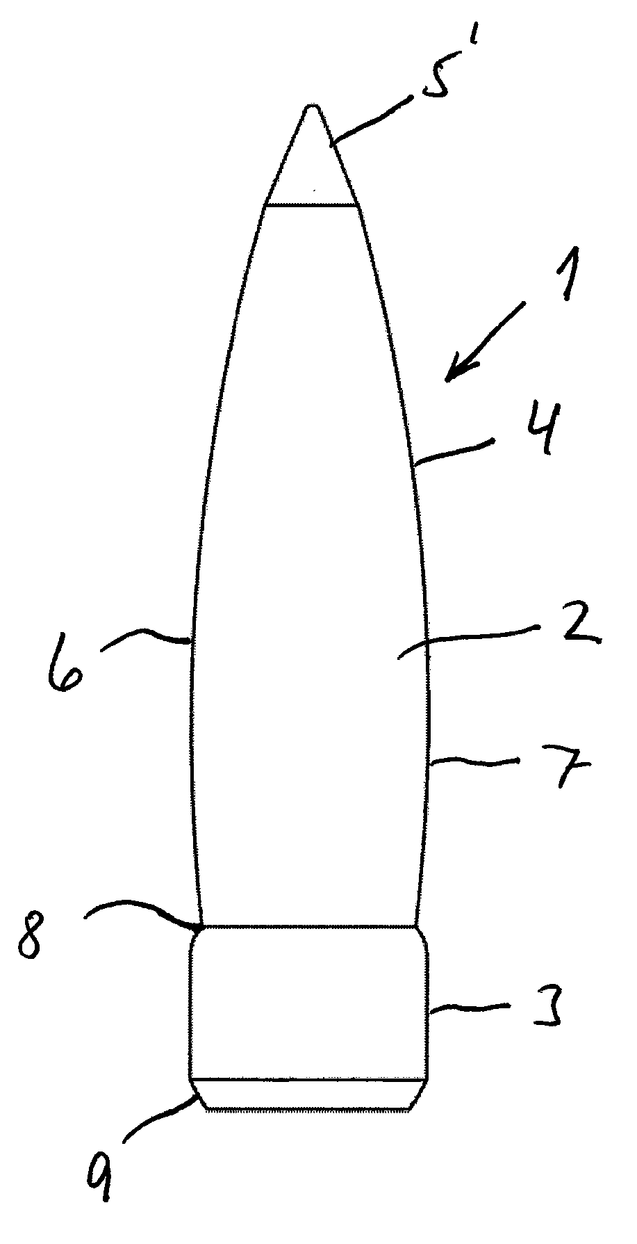
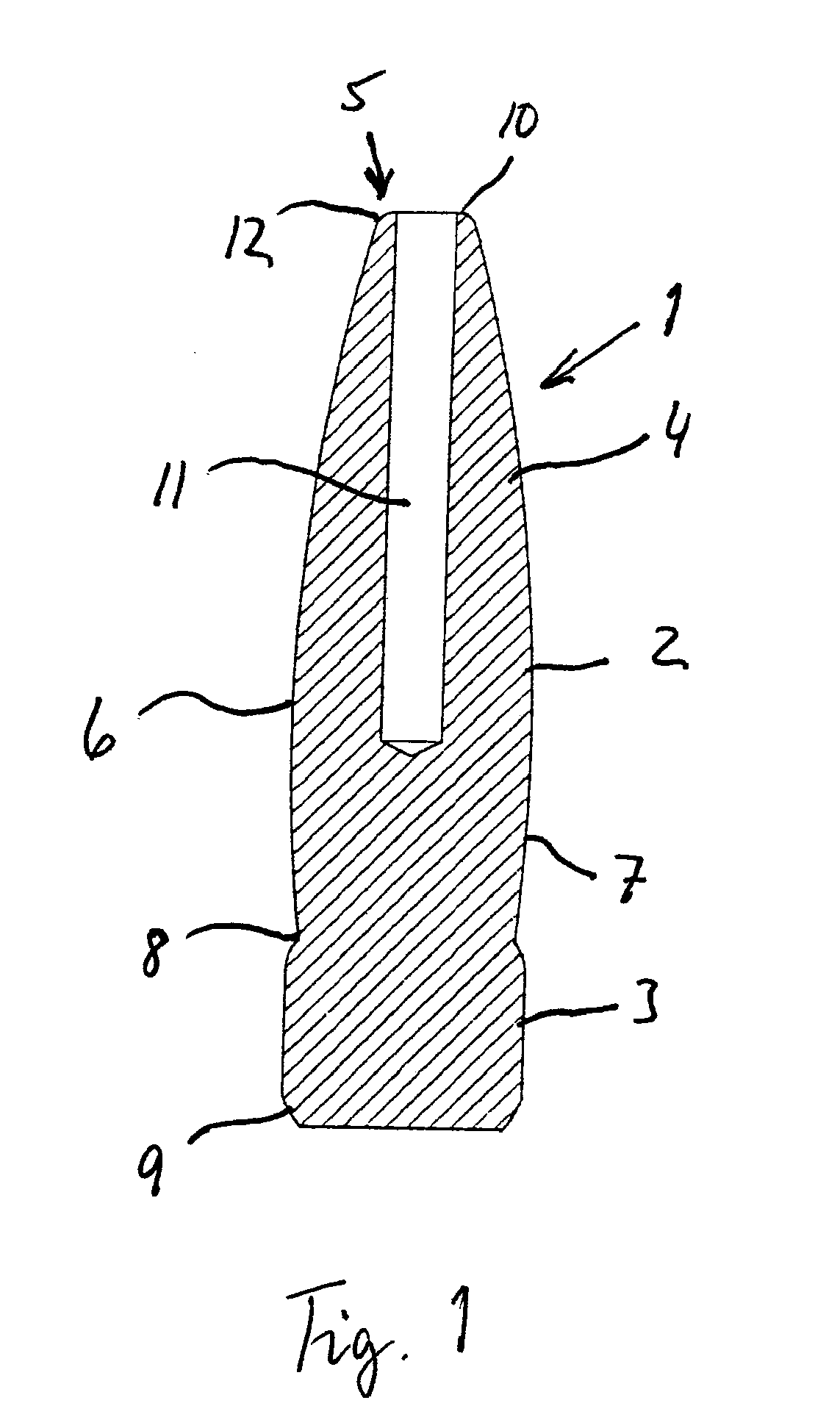
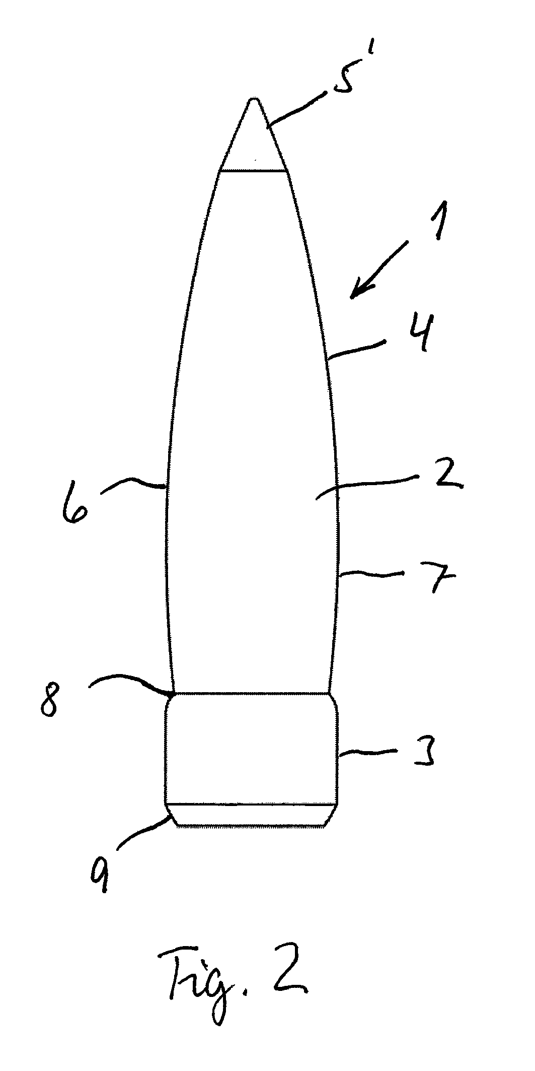
[0015]As is seen in FIG. 1, a projectile 1 for fire arms comprises a front portion 2 of essentially convex axial cross-section that via a transition 8 transforms into a rear portion 3 of essentially cylindrical cross-section. The front portion 2 is in turn divided into, on one hand, an acute portion 4, which extends, as seen in the direction of travel of the projectile, from a point 5 of the projectile 1 to an area 6 where the diameter of the projectile is maximum, at least of subcalibre, in respect of the front portion 2, and on the other hand an intermediate portion 7, which extends from the area 6 to the transition 8 between the front portion 2 and the rear portion 3.

[0016]The acute portion 4 and the intermediate portion 7 of essentially convex axial cross-section preferably have the same radius, but may, in an embodiment not shown, have different radii. This radius depends on the calibre of the fire arm. In case of a larger radius, the lands will usually penetrate into the jacke...


PUM


Abstract

A projectile for fire arms formed in such a way that it includes a front portion of essentially convex axial cross-section that via a transition transforms into a rear portion of essentially cylindrical radial cross-section, which rear portion acts as a power belt for the projectile.

Description


Claims


Application Information

Patent Timeline
Owner NORMA PRECISION AB
Learn More