
Integrated conveyor system for moving loads, in particular vehicles, along a production line

a technology of conveyor system and production line, which is applied in the direction of conveyor parts, railway components, train hauling devices, etc., can solve the problem that no sophisticated, high-cost electronic control system is required to synchronize the speed of the motors of the tts modules

Active Publication Date: 2009-03-03
CPM
View PDF13 Cites 4 Cited by
  • Summary
  • Abstract
  • Description
  • Claims
  • Application Information

AI Technical Summary

Benefits of technology

"The present invention provides a conveyor system that can be easily assembled using standard TTS conveyor modules. The system includes trucks and independent modules with grip pads and powered belts that move along rails. The trucks have stop means to form a train of trucks that can be pushed along a work line. The system also includes a brake module with an idle belt. The use of standard TTS modules reduces the size and cost of the conveyor system. The thrust imparted to each truck can be increased, allowing for longer production lines."

Problems solved by technology

Moreover, unlike a conventional TTS conveyor, no sophisticated, high-cost electronic control system is required to synchronize the speed of the motors of the TTS modules forming the production line.

Method used


Image

  • Integrated conveyor system for moving loads, in particular vehicles, along a production line
  • Integrated conveyor system for moving loads, in particular vehicles, along a production line
  • Integrated conveyor system for moving loads, in particular vehicles, along a production line

Examples


Embodiment Construction

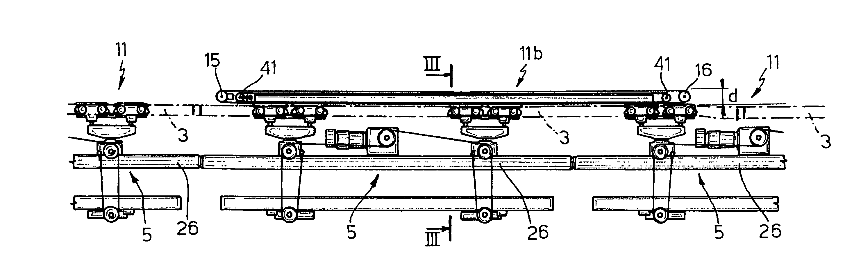
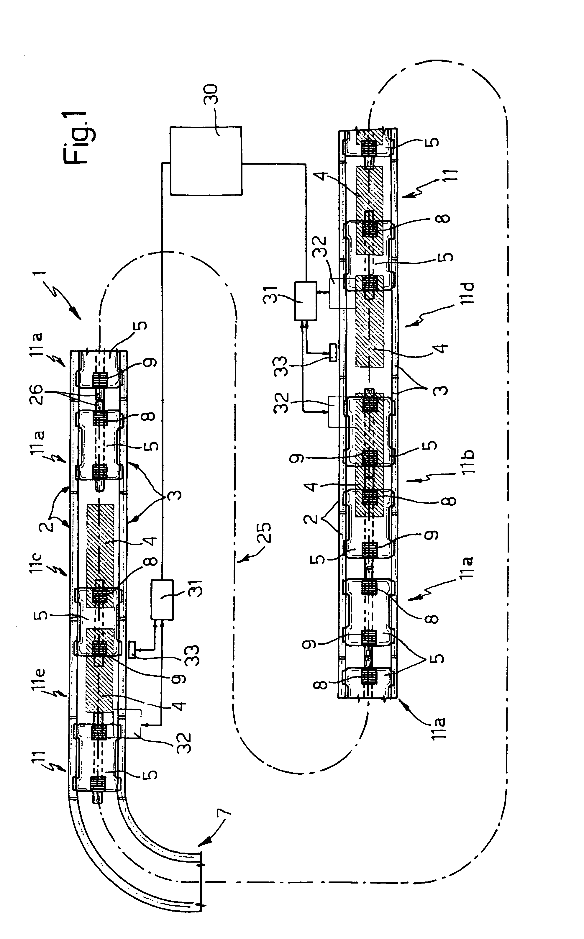
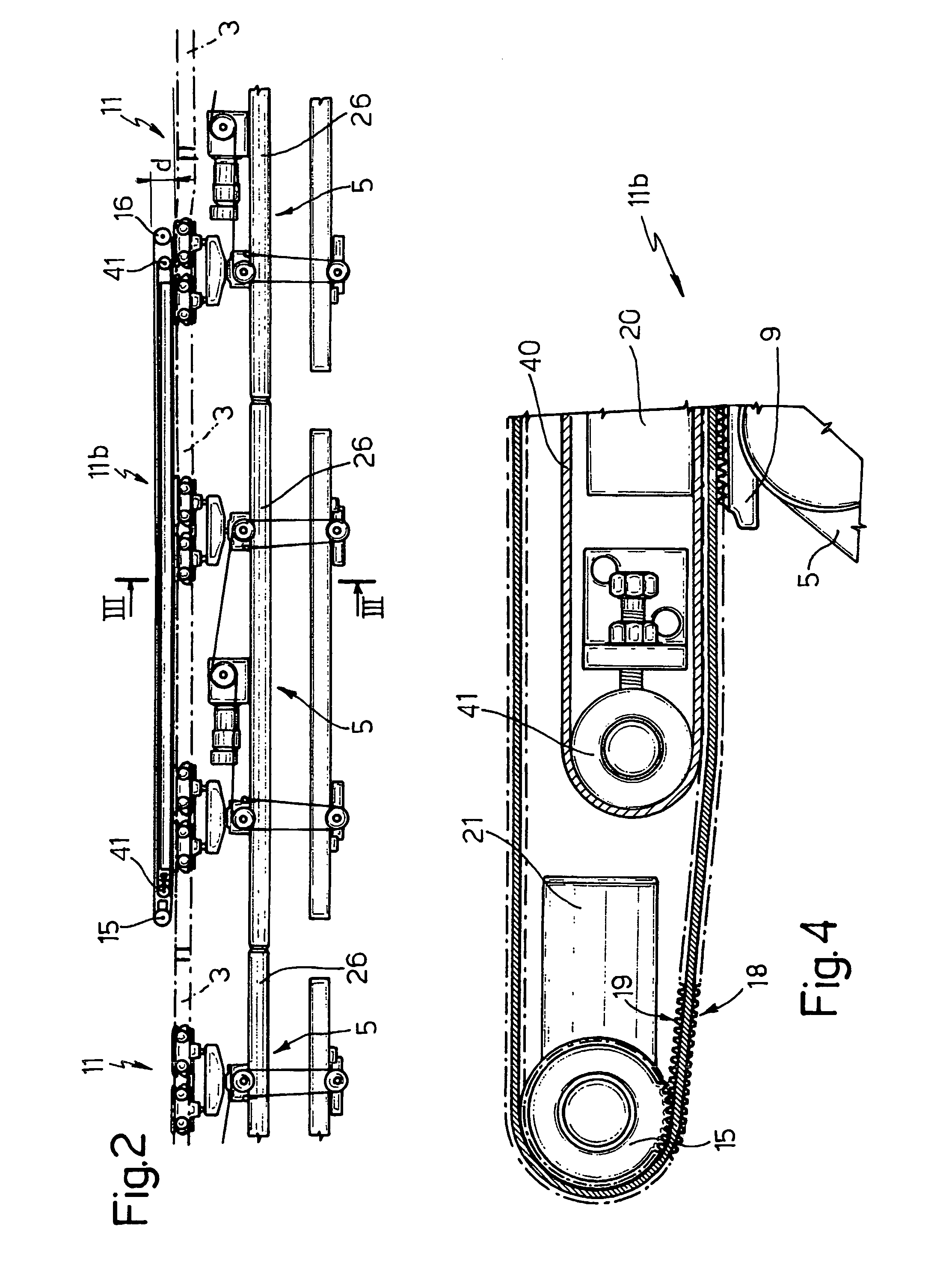
[0021]With reference to FIGS. 1 and 3, number 1 indicates as a whole an integrated conveyor system comprising a number of independent modules 11, each comprising (FIG. 3) a pair of rails 2, 3, and a powered belt 4 stretched inside the transverse space defined between the pair of rails 2, 3. Modules 11 are arranged with the pairs of rails 2, 3 end to end to form a support and guide structure 7, which is substantially continuous (except for the small assembly gap between adjacent modules) and forms an endless path of any shape (FIG. 1) for a number of trucks 5 which run along pairs of rails 2, 3.

[0022]Each truck 5 comprises a number of wheels or rollers 49 idly engaging pairs of rails 2, 3 to guide the truck both transversely and vertically; and at least one pair of grip pads 8 and 9, which, with the aid of push means 10 (FIG. 3) defined, for example, by helical springs, selectively engage powered belts 4 of modules 11, and are moved by powered belts 4 of modules 11 in a predetermined...


PUM


Abstract

The integrated conveyor system has a number of independent powered modules (11), each having a pair of rails (2, 3), and powered belt (4) stretched in the transverse space defined between the pair of rails and forming a continuous support and guide structure and along which run a number of trucks are moved by the belt of each module along the rails. The conveyor system also includes a number of modules having no powered belt, a push module (116) having a powered belt and a brake module (11c) having a nonpowered belt; the trucks having stop means for forming, a train of mutually contacting trucks between the push module and the brake module, and pushed by the powered belt of the push module.

Description

TECHNICAL FIELD[0001]The present invention relates to an integrated conveyor system for moving loads, in particular vehicles, along an assembly line.BACKGROUND ART[0002]European Patent n. 0873271, filed by the present Applicant, and the pertinent parts of which are included herein purely by way of reference, describes a modular conveyor (known commercially as TTS) comprising a number of modules powered by independent motors, and each of which comprises a contoured structure (e.g. extruded, but which can also be formed using steel sections or other methods) defining a pair of rails, and a powered belt stretched inside the transverse space between the pair of rails, over or under the rails. The modules are arranged with the pairs of rails end to end to form a substantially continuous support and guide structure defining an endless path, and along which run a number of trucks, which engage the rails with respective rollers, and each of which has at least one pair of grip pads for engag...

Claims


Application Information

Patent Timeline
Patent Type & Authority Patents(United States)
IPC IPC(8): B61J3/00B65G47/26B62D65/18B65G35/08
CPCB62D65/18B65G35/08B65G2201/0294
Inventor BELLEZZA, MASSIMO
Owner CPM
Learn More