Thermal Response Correction System for Multicolor Printing

a multicolor printing and response correction technology, applied in printing and other directions, can solve the problems of reducing the density of the output produced by reducing the efficiency of the print head element, so as to achieve the effect of reducing the differences

Active Publication Date: 2009-12-17
ZINK IMAGING
View PDF11 Cites 12 Cited by
  • Summary
  • Abstract
  • Description
  • Claims
  • Application Information

AI Technical Summary

Benefits of technology

[0039](E) adjusting the set of parameters so as to minimize the differences between the estimates of the energy required to attain the measured printed densities and the input energies supplied to the printer to achieve the measured printed densities.

Problems solved by technology

One problem with conventional thermal printers results from the fact that their print head elements retain heat after the conclusion of each print head cycle.
This retention of heat can be problematic because, in some thermal printers, the amount of energy that is delivered to a particular print head element during a particular print head cycle is typically calculated based on an assumption that the print head element's temperature at the beginning of the print head cycle is a known fixed temperature.
Further complications are similarly caused by the fact that the current temperature of a particular print head element is influenced not only by its own previous temperatures—referred to herein as its “thermal history”—but by the ambient (room) temperature and the thermal histories of other print head elements in the print head.
This gradual temperature increase results in a corresponding gradual increase in density of the output produced by the print head element, which is perceived as increased darkness in the printed image.
Furthermore, conventional thermal printers typically have difficulty accurately reproducing sharp density gradients between adjacent pixels both across the print head and in the direction of printing.
This problem results from the amount of time that is required to raise the temperature of the print head element to print the black pixel after printing the white pixel.
More generally, this characteristic of conventional thermal printers results in less than ideal sharpness when printing images having regions of high density gradient.
However, such a straightforward generalization of the media model may be inadequate for multicolor printing.
Problems that may occur include lack of a clean separation between the thermal and the media model, making it difficult to fine tune the thermal history response and / or adapt a thermal history characterization from one thermal imaging member to another; unstable or oscillatory responses to attempts to adjust the thermal model parameters to achieve a desired response; physically unreasonable values being obtained in the thermal model as a result of insufficient flexibility (in technical terms, insufficient degrees of freedom) in the media model; and non-monotonic or ill-defined responses of the thermal history control algorithm over a 3-D color space.
Note that when thermal history compensation fails in the multicolor case, not only are distortions in density possible, but distortions in color may occur as well, with objectionable results in a final image.

Method used


Image

  • Thermal Response Correction System for Multicolor Printing
  • Thermal Response Correction System for Multicolor Printing
  • Thermal Response Correction System for Multicolor Printing

Examples


Embodiment Construction

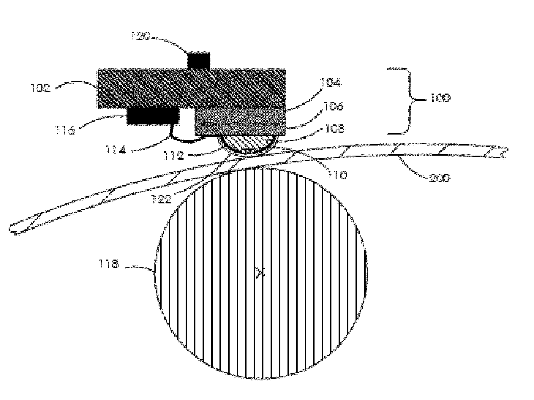
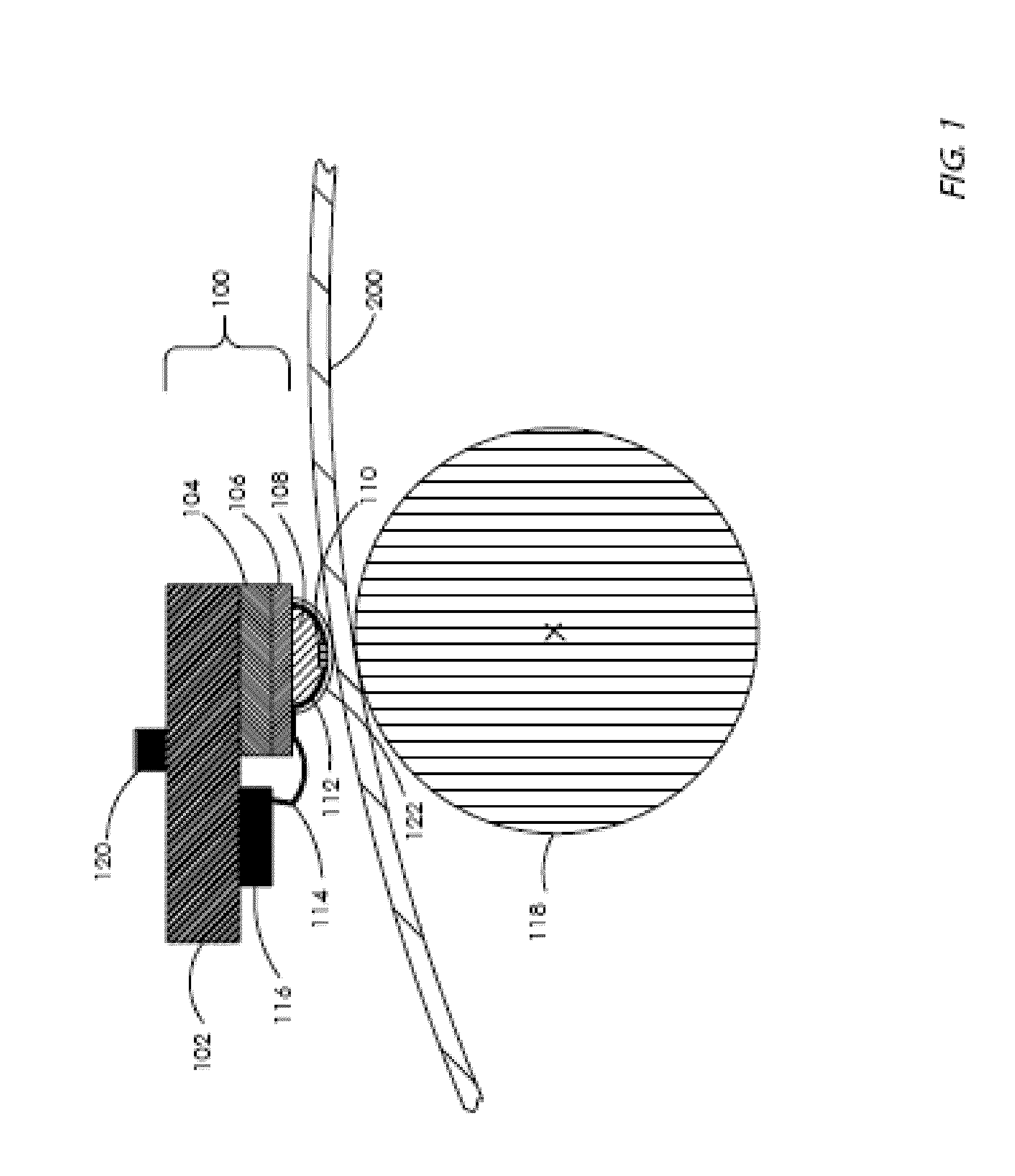
[0055]Referring now to FIG. 1, there is seen a schematic, cross-sectional view of a typical thermal printing arrangement in which a thermal printing head 100 and thermal imaging member 200 are held in intimate contact by a platen 118 (that may be a roller (as shown) or a nonrotating element) that biases the thermal imaging member 200 against thermal printing head 100. As shown in FIG. 1, a typical thermal printing head comprises a support 102 that carries both the driving circuitry 116 and the assembly comprising the print head elements. This support 102 comprises a heat sink whose temperature is monitored by a temperature measuring device 120 that may be, for example, a thermistor. The print head elements 110 are carried by a glaze layer 106 in contact with a ceramic substrate 104, and are covered by a thin, thermally-conductive overcoat 122. Ceramic substrate 104 is in contact with support 102. Shown in the figure is an optional raised “glaze bump”108 on which the print head eleme...


PUM


Abstract

Thermal history control is performed in a thermal printer in which a single thermal print head prints sequentially on multiple color-forming layers in a single pass. Each pixel-printing interval may be divided into segments, each of which may be used to print a different color. The manner in which the input energy to be provided to each print head element is selected may be varied for each of the segments. Different energy computation functions may be used to compute the energy to be provided to the print head in each of the segments based on the predicted print head element temperature at the beginning of the segment, the color to be printed, and the energy that was supplied when printing other colors during the time period between the beginning of the segment of the current pixel-printing interval and the end of the equivalent segment of the previous pixel-printing interval.

Description

CROSS REFERENCE TO RELATED APPLICATIONS[0001]This application claims priority from U.S. Prov. Pat. App. Ser. No. 61 / 061,112, filed Jun. 13, 2008, entitled, “Thermal Response Correction System for Multicolor Printing,” which is hereby incorporated by reference herein.[0002]This application is related to the following United States patents and patent applications, which are hereby incorporated by reference:[0003]U.S. Pat. No. 6,819,347, which describes and claims a method for compensation of distortions induced by thermal history in a thermal printer;[0004]U.S. Pat. No. 7,176,953, which describes and claims a method for thermal history compensation in a thermal printer that includes a correction for the temperature of a thermal imaging member;[0005]U.S. Pat. No. 7,295,224, which describes and claims a method for thermal history compensation in a thermal printer that includes corrections for ambient temperature and humidity;[0006]U.S. Pat. No. 7,298,387, which describes and claims a me...

Claims


Application Information

Patent Timeline
Patent Type & Authority Applications(United States)
IPC IPC(8): B41J2/00
CPCB41J2/365B41J2/3555
Inventor SAQUIB, SUHAIL S.
Owner ZINK IMAGING
Why Eureka
Try Eureka