Rotary Connector Device

a technology of rotary connectors and connectors, which is applied in the direction of coupling device connections, cable arrangements between relatively moving parts, transportation and packaging, etc., can solve the problems of bringing the erroneous assembly, the flexible cable which has run on the ribs may be damaged, and the flexible cable which has run on the ribs may slide into and fall between the ribs, so as to restrict or prevent an increase of surface pressure, and easy to find the er

Inactive Publication Date: 2009-12-24
NILES PARTS CO LTD
View PDF32 Cites 18 Cited by
  • Summary
  • Abstract
  • Description
  • Claims
  • Application Information

AI Technical Summary

Benefits of technology

[0014]A rotary connector device according to an aspect of the present invention comprises a fixed-side member which is supported to a vehicle body side and through which a steering shaft penetrates, a rotary-side member which is rotatably connected to the fixed side member and through which the steering shaft penetrates, and rotatable in response to rotation of a steering wheel, a free motion spacer including a group of spacer sections arranged circularly between the fixed-side member and the rotary-side member and a reverse guide section in which a guide face is provided to be opposed to any one of the spacer sections in the group of spacer sections in the circumferential direction to form a reverse insert section and capable of turning with rotation of the rotary-side member, and a flexible cable which is reversed by inserting a reverse section into the reverse insert section of the free motion spacer and is wound around outer and inner peripheral sides of the group of spacer sections, the rotary connector device further comprising an interposing section provided in a wall face of the reverse guide section in the opposing side of the guide face in the circumferential direction of the reverse guide section to be positioned between the wall face and the space section adjacent to the wall face, a projection for a stopper provided at the interposing section to project toward the direction of a rotational axis of the free motion spacer, whereby when the reverse section of the flexible cable is erroneously assembled between the wall face and the spacer section adjacent to the wall face, the reverse section runs on the interposing section and the projection can restrict the reverse section to fall down from the interposing section.
[0015]Therefore, when the free motion spacer is combined to a casing at the time the erroneous assembly is generated, a floating gap is generated between the free motion spacer and the casing by the flexible cable which has run on the interposing section, making it possible to easily find the erroneous assembly of the flexible cable. Therefore, the interposing section and the projection can restrict the erroneous assembly of the flexible cable.
[0016]Further, since the interposing section is positioned between the wall face in the reverse guide section at the opposing side of the guide face and the spacer section, the axis length of each spacer section is not influenced. Therefore, it is possible to restrict or prevent an increase of a surface pressure which the flexible cable receives from the spacer section due to maintaining the axis length of each spacer section.
[0017]In addition, the projection provided at the interposing section can prevent the erroneous assembly to be caused by the sliding of the flexible cable on the interposing section and the falling-down of the flexible cable.
[0018]An object of the present invention of restricting or preventing an increase of a surface pressure which a flexible cable receives from a spacer section while preventing an erroneous assembly by an interposing section is realized by the interposing section provided at a wall face of a reverse guide section in the opposing side of a guide face in the reverse guide section and a projection provided in the interposing section.

Problems solved by technology

In consequence, durability of the flexible cable may be damaged.
However, the flexible cable which has run on the ribs possibly slides into and falls down between the ribs.
When the flexible cable falls down between the rib having no projection at the base section and the roller, it possibly brings the erroneous assembly.
In consequence, durability of the flexible cable may be damaged.
In addition, the flexible cable which has run on the ribs provided for preventing the erroneous assembly slides on the ribs and falls down between the ribs, possibly bringing the erroneous assembly.

Method used


Image

  • Rotary Connector Device
  • Rotary Connector Device
  • Rotary Connector Device

Examples


first embodiment

[0030][Rotary Connector Device]

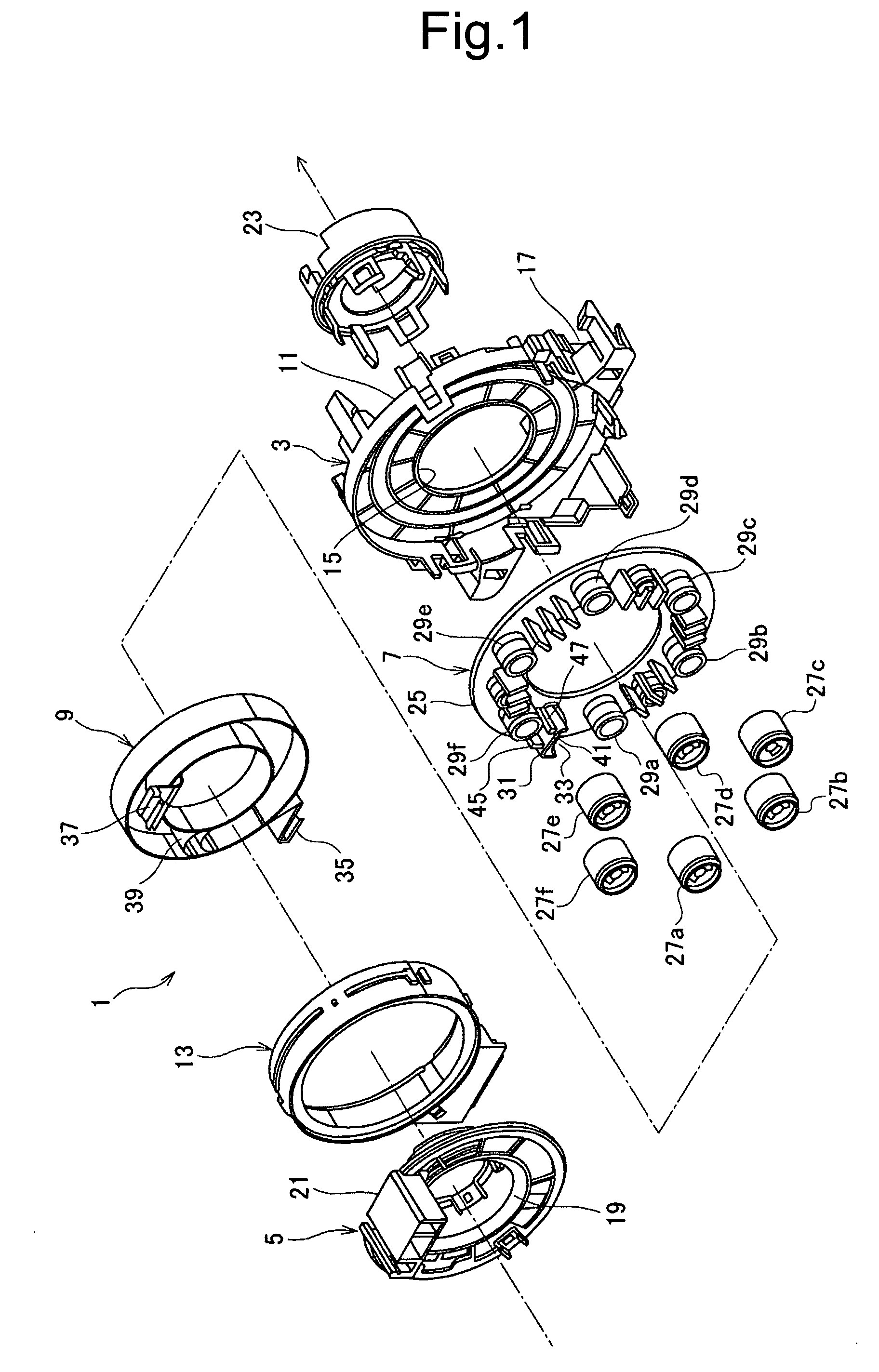
[0031]FIG. 1 is an entire exploded perspective view showing a rotary connector device according to a first embodiment of the present invention.

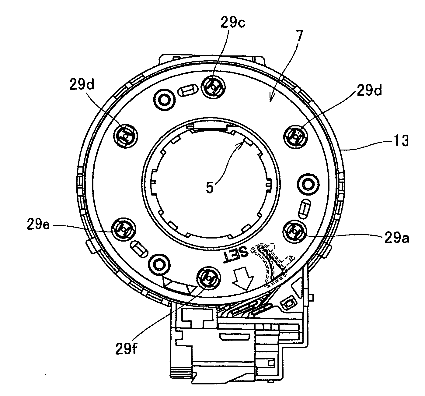
[0032]The rotary connector device 1 in FIG. 1 serves to electrically connect a horn, an air bag and the like located in the side of a steering wheel in an automobile to the side of a vehicle body. The rotary connector device 1 is provided with a body 3 as a fixed-side member, a rotor (spacer section) 5 as a rotary-side member, a free motion spacer 7, and a flat cable 9 as a flexible cable.

[0033]The body 3 is provided with a bottom cover 11 and a casing 13 engaged with the bottom cover 11. The bottom cover 11 is fixed to the side of a combination switch fixed to a steering column (not shown).

[0034]The bottom cover 11 is formed in a donut shape with resin or the like, and is provided with a fixed-side hole section 15 formed at the central portion through which a steering shaft penetrates and a fixed-side terminal ...


PUM


Abstract

There are provided a body, a rotor, a free motion spacer including a group of spacer sections arranged circularly between the body and the rotor and a reverse guide section in which a guide face is provided to be opposed to a roller in the group of spacer sections in the circumferential direction to form a reverse insert section and capable of turning with rotation of the rotor, and a flat cable which is reversed by inserting the reverse section into the reverse insert section in the free motion spacer and is wound around the outer and inner peripheral sides of the group of spacer sections where ribs 45 and 47 project from a wall face at the opposing side of a guide face toward the roller adjacent to the wall face in the circumferential direction of the reverse guide section, and a projection 49 for the stopper is provided in the rib, whereby when the reverse section of the flat cable is erroneously assembled between the wall face and the roller adjacent to the wall face, the reverse section runs on the rib and the projection can restrict the reverse section to fall down from the rib.

Description

CROSS-REFERENCE TO RELATED APPLICATION[0001]This application claims priority under 35 USC 119 from Japanese Patent Application No. 2008-160648, the disclosure of which is incorporated by reference herein.BACKGROUND OF THE INVENTION[0002]1. Field of the Invention[0003]The present invention relates to a rotary connector device supplied for electrical connection between a vehicle body and a steering wheel in an automobile.[0004]2. Description of Related Art[0005]In the conventional rotary connector device, a flexible cable is assembled in a member except for a specific reverse insert section and the erroneous assembly in a state where the flexible cable is attached in the wrong position possibly goes to the next process.[0006]For preventing such an erroneous assembly, as shown in FIG. 3 in Japanese Patent Laid-Open No. 06-338372, a rotary connector device is configured in such a manner that ribs are provided in a member except for the reverse insert section, and a flexible cable runs o...

Claims


Application Information

Patent Timeline
Patent Type & Authority Applications(United States)
IPC IPC(8): H01R33/00
CPCB60R16/027H01R2201/26H01R35/025H02G11/00
Inventor OISHI, HIROSHISATO, TOMOHIRO
Owner NILES PARTS CO LTD
Why Eureka
Try Eureka