Supercharge Your Innovation With Domain-Expert AI Agents!

Methods for manufacturing a paint roller with perforated substrate

a technology of perforated substrates and manufacturing methods, applied in metal working apparatuses, chemistry apparatus and processes, other domestic objects, etc., can solve the problems of paint rollers made out of cores, paint rollers that are easily damaged, and require a long assembly line, so as to achieve superior, light weight, and inexpensive paint rollers

Active Publication Date: 2009-12-31
SEKAR CHANDRA
View PDF64 Cites 14 Cited by
  • Summary
  • Abstract
  • Description
  • Claims
  • Application Information

AI Technical Summary

Benefits of technology

[0033]The embodiments comprise a novel combination that uses two strips of polypropylene material to provide an method and apparatus for making superior, light weight, and inexpensive paint rollers.

Problems solved by technology

Such cores, however, and the paint rollers made out of them, would often fall apart during use or during cleaning, especially during cleaning with paint solvents (such as, for example, turpentine or mineral spirits, such paint solvents are well known in the art).
The obvious drawback of reusable cores formed in this manner is that they require a long assembly line, due to the need of a heater, and because the phenolic must be heated to a predetermined temperature, there is an obvious trade off between the number of heater stages and the speed of the line.
Additionally, while the resulting rollers are termed reusable because they do not separate when placed in paint solvents, any prolonged exposure to such solvents, does result in breakdown of the paint roller and / or separation of the layers.
Moreover, the manufacturing process for making phenolic core rollers is environmentally unfriendly.
For one, while prior art techniques use rolls of, e.g., chipboard or paper, the Garcia process requires preformed thermoplastic tubular cores which are considerably bulkier than rolls, more expensive to transport, and more difficult to handle.
Another drawback is the anticipated speed limit of the Garcia process dictated by the necessity that the heater, which advances along the core just in front of the fabric strip, move slow enough to insure softening of the polypropylene core, in the absence of which the fabric cover will not bond.
In addition, the application of direct heat to the preformed polypropylene core presents manufacturing hazards from the heat source and from the fumes and / or chemicals released during the heating process.
As a result, the process was difficult to set up, and required many continuous adjustments in its operation.
The resulting roller, however, is somewhat inferior.
More specifically, a defect present in all such rollers, manifests itself as a weak point, often sticking out from the ends of a cut roller, or making the ends of the cut roller appear “out of round.” This results from the high tension memory of the strip which tends toward unwinding or toward “open” with high hoop strength.
The application of fluidized polypropylene to a mandrel has concomitant complications in synchronization and in the problems inherent in working with consistency of application of a fluidized layer in forming a polypropylene core.
It is, however, believed that no such systems have the difficulties associated with controlling the shrinkage variation which inevitably occurs in the matching of what is essentially a through heated core blank or strip blank and a cold (i.e., room temperature, for example) pile fabric.

Method used


Image

  • Methods for manufacturing a paint roller with perforated substrate
  • Methods for manufacturing a paint roller with perforated substrate
  • Methods for manufacturing a paint roller with perforated substrate

Examples


Embodiment Construction

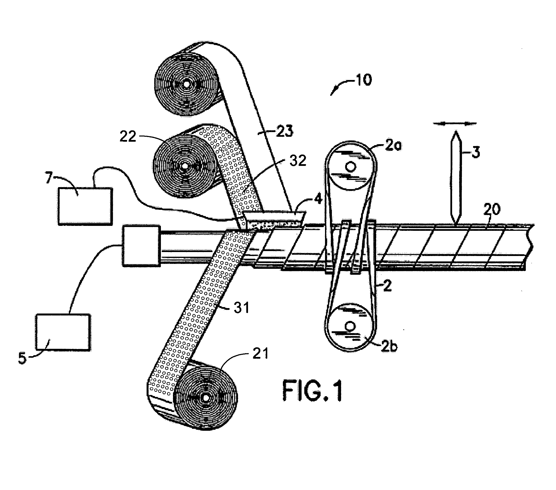
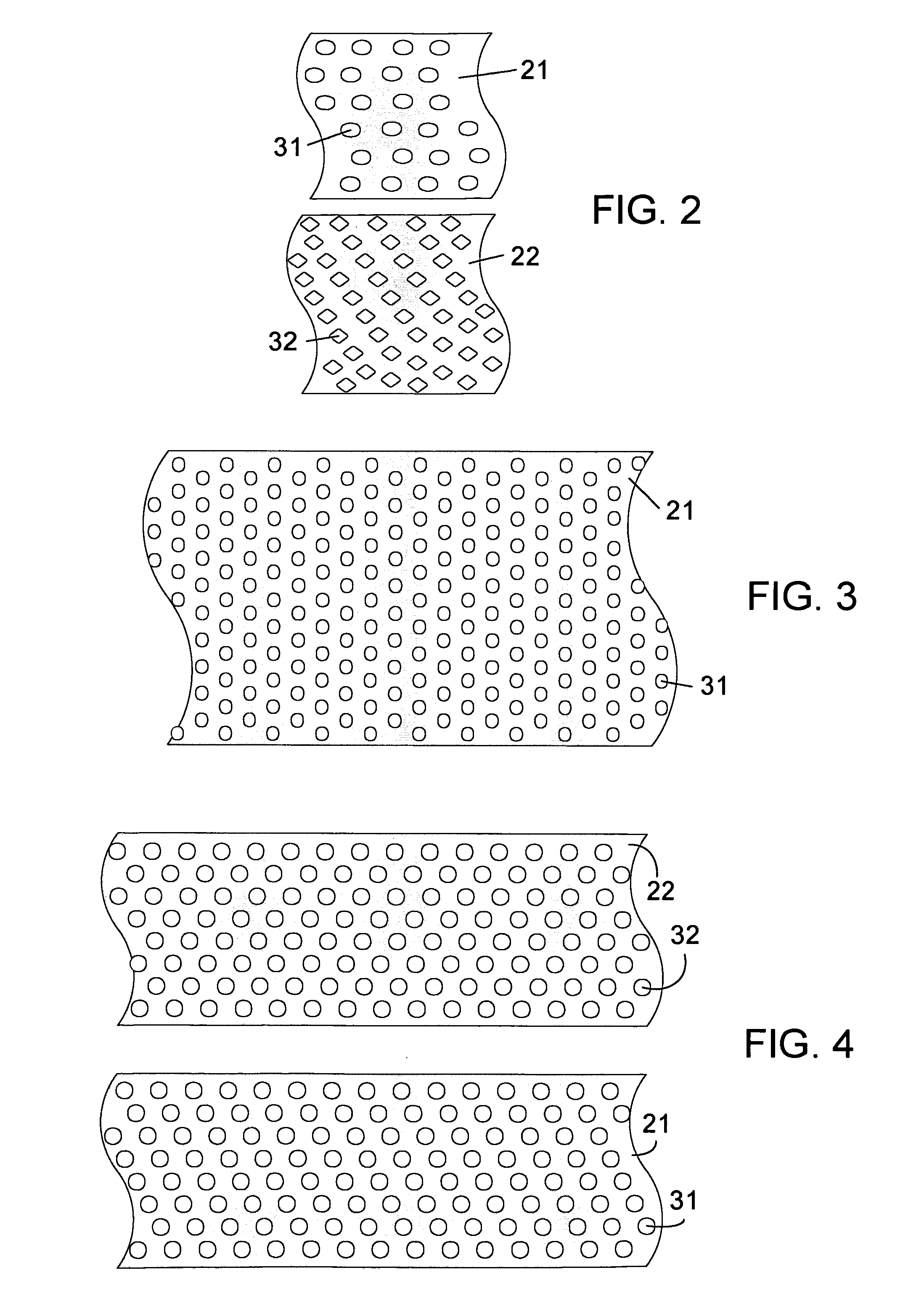
[0044]In the embodiment shown in FIG. 1, a roller forming apparatus 10 comprises a stationary mandrel 1, cooled by cooler 5, on which the roller 20 is formed, helical drive belt 2 moves by between drive rollers 2a and 2b to turn and move the formed endless roller 20 along the mandrel 1 to a fly-away cutter 3. A paint roller is manufactured from an inner strip of thermoplastic material 21, an outer strip of thermoplastic material 22, a cover 23, and an adhesive 6 applied from one or more heads 4. The thermoplastic material is preferably polypropylene. The strips 21, 22 have been perforated and contain holes 31, 32, respectively. The cover 23 may be a well-known fabric cover for a paint roller, which can be made of polyester.

[0045]For ease of discussion in this application, the term “downstream” refers to the direction further along in the roller manufacturing process, or nearer the fly-away cutter 3, while the term “upstream” refers to the direction earlier in the roller manufacturin...


PUM

PropertyMeasurementUnit
Diameteraaaaaaaaaa
Fractionaaaaaaaaaa
Weightaaaaaaaaaa

Abstract

A method for reducing cost and weight in paint roller manufacturing processes and other continuous processes for producing tubular goods from polymers. The method may utilize a perforated substrate such as a perforated polypropylene strip or may include a perforating step which removes overage from an unperforated substrate. The perforated substrate is fed onto a mandrel to form a tube. Adhesive is applied upon the outer surface of the perforated substrate. A cover may be applied about the tube, and the resulting product is then cut into finished-size paint rollers. The removal of the overage results in a reduction in the weight of the paint roller. In certain embodiments the overage from a perforation step is collected, and may be reused in a subsequent implementation of the method or resold.

Description

[0001]This application includes material which is subject to copyright protection. The copyright owner has no objection to the facsimile reproduction by anyone of the patent disclosure, as it appears in the Patent and Trademark Office files or records, but otherwise reserves all copyright rights whatsoever.FIELD OF THE INVENTION[0002]This invention pertains to a method and apparatus for making paint rollers of the type used for applying paint to walls and the like. More specifically, the invention pertains to a method and apparatus for making paint rollers formed in a continuous process from perforated strips.BACKGROUND OF THE INVENTION[0003]Paint rollers are widely used by professionals and amateurs for applying paint to walls, ceilings, and other surfaces. Typically the roller is used with an applicator having a handle terminating in a rotatable member to which the roller is secured. The roller itself generally comprises a paint absorbing and spreading cover affixed to a generally...

Claims


Application Information

Patent Timeline
IPC IPC(8): B32B38/04
CPCB26D1/56Y10T156/1056B26D3/164B26F1/10B29B13/024B29C53/607B29C59/103B29C59/142B29C65/10B29C65/5057B29C65/52B29C65/525B29C66/1142B29C66/30325B29C66/43B29C66/45B29C2035/0822B29C2793/0045B29C2793/009B29D23/001B29K2023/12B29K2067/00B29K2101/12B29K2623/12B29L2009/00B29L2023/00B29L2031/328B29L2031/737B26D3/16B29C66/4329B29C66/4322B29C65/483B29C65/4815B29C65/524B29C65/5021B29C65/00B29C66/83433B29C66/49B29C66/496B29C66/71B29C66/1122
Inventor SEKAR, CHANDRA
Owner SEKAR CHANDRA
Features
  • R&D
  • Intellectual Property
  • Life Sciences
  • Materials
  • Tech Scout
  • Unparalleled Data Quality
  • Higher Quality Content
  • 60% Fewer Hallucinations
Learn More