Method and system using GNSS phase measurements for relative positioning

a technology of phase measurement and relative positioning, applied in vehicle position/course/altitude control, process and machine control, instruments, etc., can solve the problems of ionospheric refraction errors, ionospheric refraction errors, and the process of position determination is subject to clock reference errors. , to achieve the effect of eliminating substantial clock variation

Active Publication Date: 2009-12-31
HEMISPHERE GNSS
View PDF99 Cites 115 Cited by
  • Summary
  • Abstract
  • Description
  • Claims
  • Application Information

AI Technical Summary

Benefits of technology

[0013]Disclosed herein in an exemplary embodiment is a method for measuring relative position of fixed or slow-moving points in close proximity comprising: receiving a set of satellite signals with a first receiver corresponding to a first position; receiving a related set of satellite signals with a second receiver corresponding to a second position; and computing a posit

Problems solved by technology

In stand-alone GPS systems that determine a receiver's position coordinates without reference to a nearby reference receiver, the process of position determination is subject to errors from a number of sources.
These include errors in the satellite's clock reference, the location of the orbiting satellite, ionospheric refraction errors (which delay GPS code signals but advance GPS carrier signals), and tropospheric induced delay errors.
SA would often cause positioning errors exceeding 40 meters, but even today, with SA off, errors caused by the ionosphere can be tens of meters.
Another error source, which is present in the carrier phase measurements, is the clock difference between the two receivers.
This reduces the number of usable satellite measurements by one.
One of the difficulties in perfor

Method used


Image

  • Method and system using GNSS phase measurements for relative positioning
  • Method and system using GNSS phase measurements for relative positioning
  • Method and system using GNSS phase measurements for relative positioning

Examples


Embodiment Construction

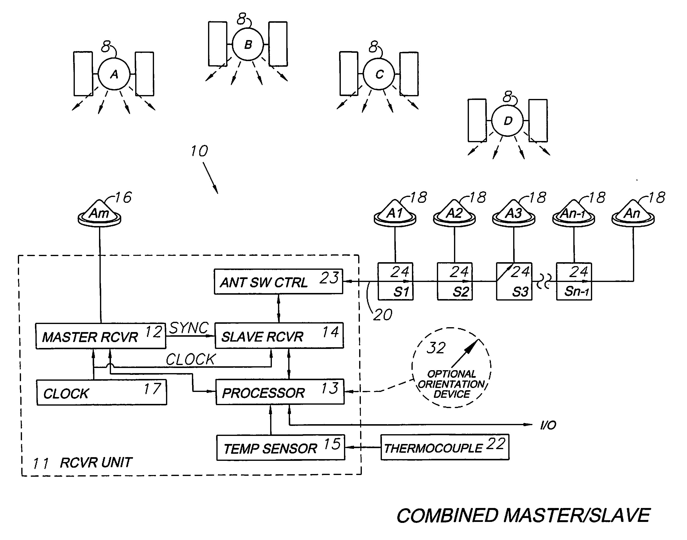
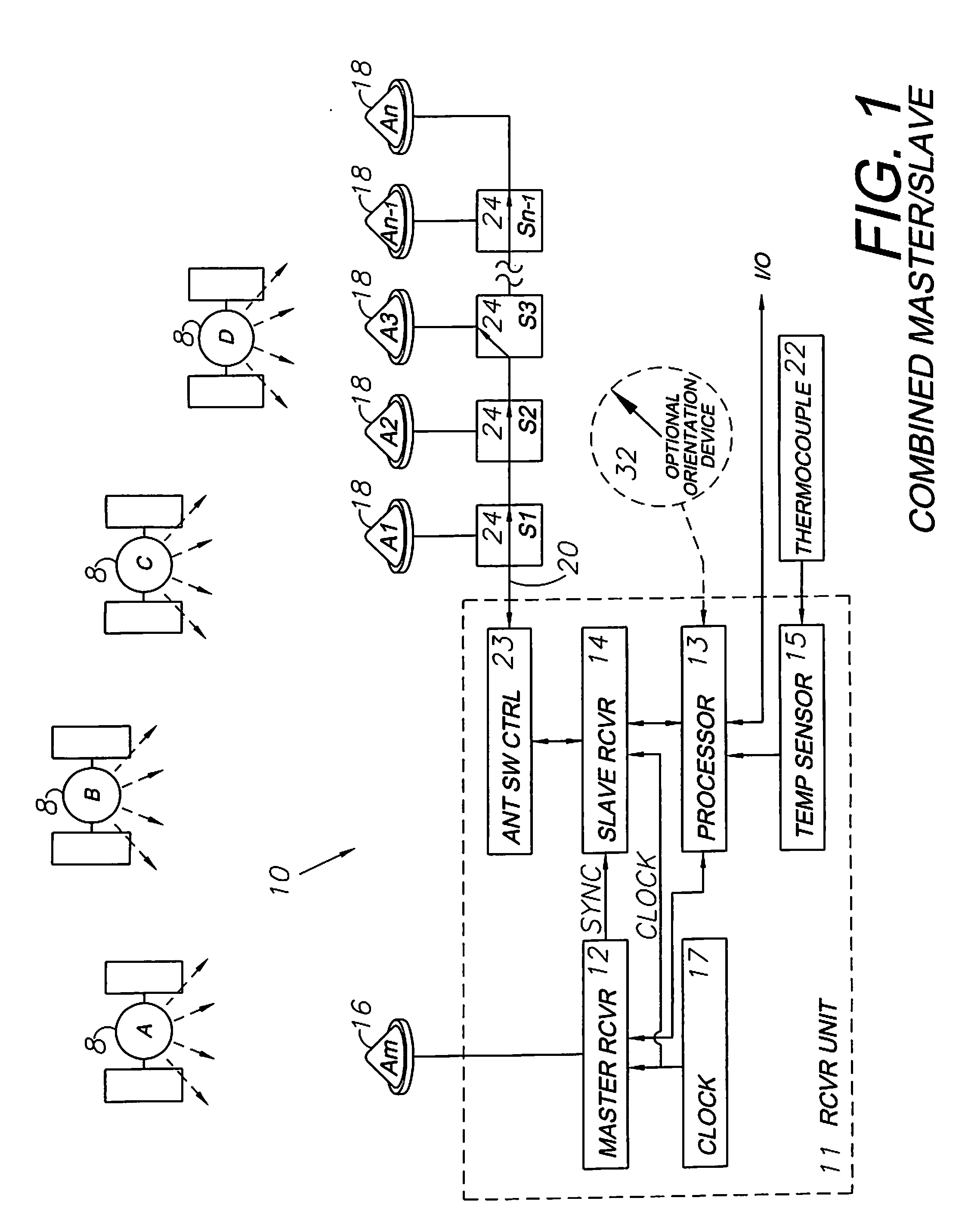
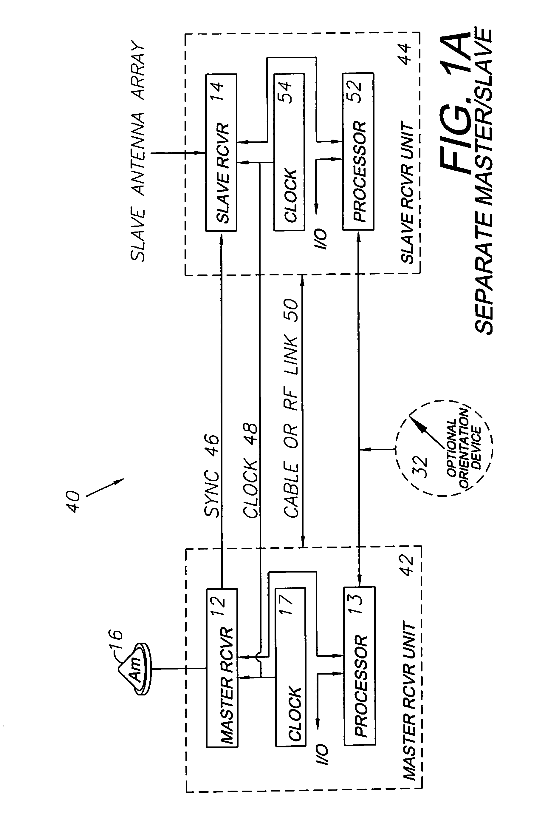
[0025]As required, detailed embodiments of the present invention are disclosed herein; however, it is to be understood that the disclosed embodiments are merely exemplary of the invention, which may be embodied in various forms. Therefore, specific structural and functional details disclosed herein are not to be interpreted as limiting, but merely as a basis for the claims and as a representative basis for teaching one skilled in the art to variously employ the present invention in virtually any appropriately detailed structure. Certain terminology will be used in the following description for convenience in reference only and will not be limiting. For example, up, down, front, back, right and left refer to the invention as oriented in the view being referred to. The words “inwardly” and “outwardly” refer to directions toward and away from, respectively, the geometric center of the embodiment being described and designated parts thereof. Global navigation satellite systems (GNSS) ar...


PUM


Abstract

A method for locating GNSS-defined points, distances, directional attitudes and closed geometric shapes includes the steps of providing a base with a base GNSS antenna and providing a rover with a rover GNSS antenna and receiver. The receiver is connected to the rover GNSS antenna and is connected to the base GNSS antenna by an RF cable. The receiver thereby simultaneously processes signals received at the antennas. The method includes determining a vector directional arrow from the differential positions of the antennas and calculating a distance between the antennas, which can be sequentially chained together for determining a cumulative distance in a “digital tape measure” mode of operation. A localized RTK surveying method uses the rover antenna for determining relative or absolute point locations. A system includes a base with an antenna, a rover with an antenna and a receiver, with the receiver being connected to the antennas. A processor is provided for computing positions, directional vectors, areas and other related tasks.

Description

CROSS-REFERENCES TO RELATED APPLICATIONS[0001]This application is a continuation-in-part of and claims the benefit of: U.S. patent applications Ser. No. 12 / 355,776 (4007.2), filed Jan. 8, 2009, which is a continuation-in-part of and claims the benefit of No. 12 / 171,399 (4007.1), filed Jul. 11, 2008, which is a continuation-in-part of and claims the benefit No. 10 / 804,758 (4007), filed Mar. 19, 2004, now U.S. Pat. No. 7,400,956; and No. 12 / 171,399 (4011.1), filed Jul. 11, 2008, which is a continuation-in-part of and claims the benefit of No. 10 / 828,745 (4011), filed Apr. 21, 2004; and U.S. Provisional Patent Applications No. 60 / 456,146, filed Mar. 20, 2003, and No. 60 / 464,756, filed Apr. 23, 2003. The contents of all of the aforementioned applications are incorporated by reference herein in their entireties.BACKGROUND OF THE INVENTION[0002]The invention relates generally to Global Navigation Satellite System (GNSS) receivers and more particularly to a method and an apparatus for comp...

Claims


Application Information

Patent Timeline
IPC IPC(8): G01S1/00
CPCG01C15/00G01S5/0063G01S19/14G01S19/36G05D1/0278G05D1/0206G05D1/0259G05D1/027G01S19/53
Inventor WHITEHEAD, MICHAEL L.MILLER, STEVEN R.MCCLURE, JOHN A.DAVIS, CARYFELLER, WALTER J.
Owner HEMISPHERE GNSS
Why Eureka
Try Eureka