
Aircraft door and method for using the same

a technology for aircraft and doors, applied in door/window fittings, mechanical equipment, transportation and packaging, etc., can solve problems such as inability to operate cables, improper locking of doors, and design malfunctions,

Active Publication Date: 2010-01-07
BE AEROSPACE INCORPORATED
View PDF14 Cites 13 Cited by
  • Summary
  • Abstract
  • Description
  • Claims
  • Application Information

AI Technical Summary

Benefits of technology

The present invention relates to an integrated latching / locking system for aircraft external doors, which solves the problems of previous designs such as susceptibility to malfunction caused by icing and complexity. The invention minimizes parts count and complexity, while eliminating the reliability issues caused by icing and other adverse conditions. The invention provides an independent lock for the latch system, which ensures safety and reliability. The invention also includes a monitoring system that can detect and prevent unauthorized access to the door. The technical effects of the invention include improved safety and reliability, simplified design, and efficient manufacturing process.

Problems solved by technology

Many forms of doors exist for cargo loading and unloading; however, these designs suffer from a number of weaknesses, including susceptibility to malfunction caused by icing of door components, leading to the possibility that an aircraft may take off with a door improperly secured.
Previous designs have used cable-actuated monitoring systems to indicate successful door closure; however, these designs are subject to malfunction due to icing.
The difficulty in creating a hermetic seal between the actuating cable and the cable housing leads to formation of ice inside the cable housing, rendering the cable inoperative.
Additionally, prior designs have utilized latching systems that require a dwell in the latching actuation.
This introduces additional cost and complexity into the design.
Furthermore, existing designs do not provide an independent lock for the latch system, leading to the possibility that ground loads or in-flight forces could create a torque on the system and possibly unlatch the door in the event of a failure in the lock system.

Method used


Image

  • Aircraft door and method for using the same
  • Aircraft door and method for using the same
  • Aircraft door and method for using the same

Examples


Embodiment Construction

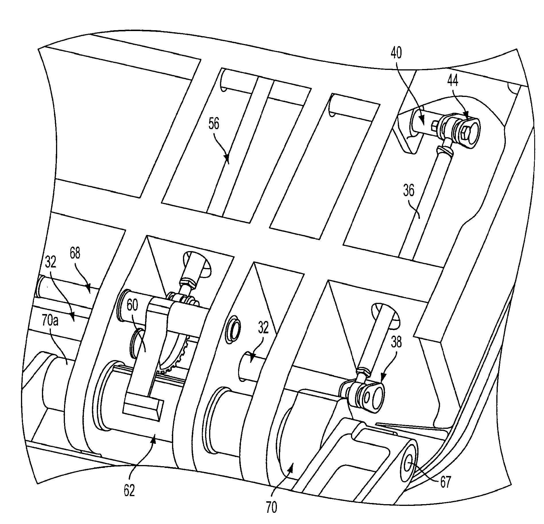
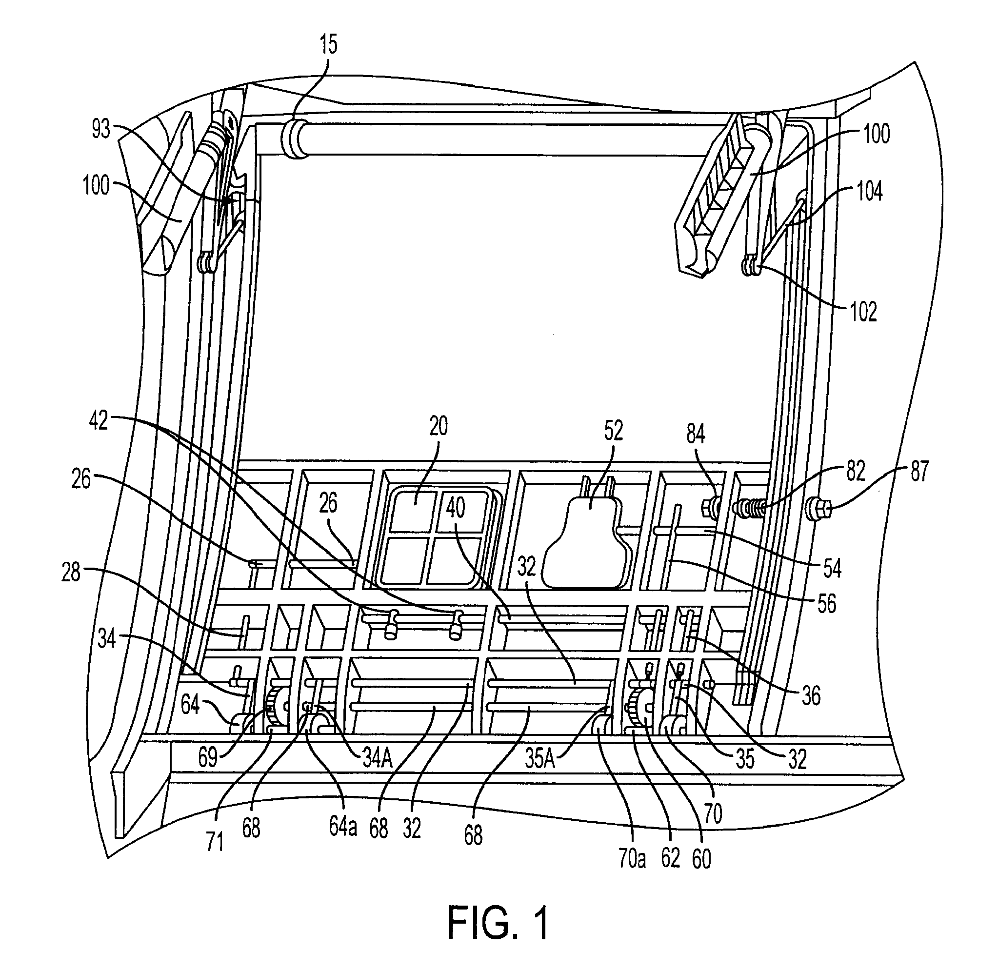
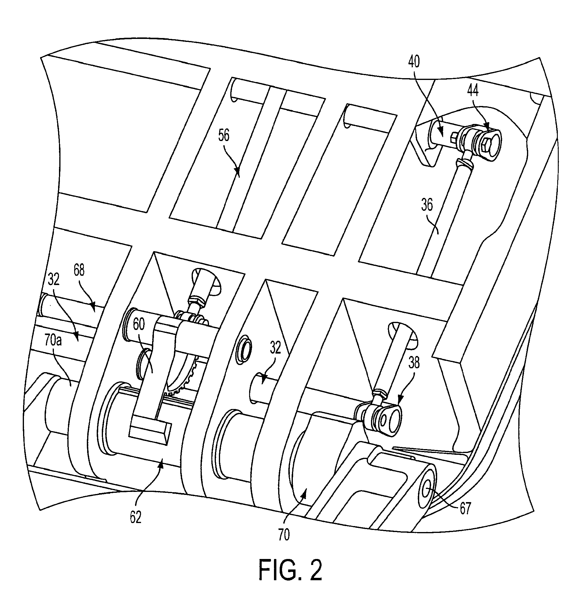
[0033]The exemplary embodiments of the invention described herein relate to an aircraft door. The door in these embodiment is used to access the cargo area of the aircraft from the exterior of the craft. The door includes a locking system, a latching system featuring an integrated lock, an actuating system, and safety features, including a lock monitoring system, a latch handle interlock, and an uplock system to secure the door in an open position.

[0034]The locking system in this example is actuated by a vent door, and both immobilizes the door's latching system and ensures that the aircraft cannot be pressurized for flight unless the vent door is properly closed. The system includes a monitoring system that prevents closure of the vent door, and thus pressurization of the aircraft, if there is a malfunction in the locking system. The locking system prevents movement of the components of the latching system. The latching system, like the lock system and monitoring system, relies on,...


PUM


Abstract

An external door for use in accessing a cargo area of an aircraft fuselage. The door includes a locking system, a latching system, a lock monitoring system, an uplock used to secure the door in an open position, and an actuating system that assists in at least one of opening and closing the door. The locking system works by interfering with the movement of the latching system components. The locking system includes a monitoring device that prevents the aircraft from being pressurized in case of a malfunction in the locking system. The latching system includes a handle locking system that prevents operation of the latch handle by accident or by ground loading or flight forces. The systems of the door are preferably manually operated, and utilize rigid members.

Description

CROSS-REFERENCE TO RELATED PATENT APPLICATIONS[0001]This application claims priority to U.S. provisional patent application 60 / 953,148, filed Jul. 31, 2007, which is incorporated in its entirety herein by reference.FIELD OF THE INVENTION[0002]The present invention relates generally to aircraft external doors, and more particularly to latching and locking mechanisms for such doors.BACKGROUND OF THE INVENTION[0003]Many aircraft include an external door for accessing an aircraft cargo area. Cargo areas typically utilize upward-opening, canopy-style doors, as opposed to the side-opening, plug-style doors used for passenger ingress and egress. Many forms of doors exist for cargo loading and unloading; however, these designs suffer from a number of weaknesses, including susceptibility to malfunction caused by icing of door components, leading to the possibility that an aircraft may take off with a door improperly secured. Previous designs have used cable-actuated monitoring systems to ind...

Claims


Application Information

Patent Timeline
Patent Type & Authority Applications(United States)
IPC IPC(8): B64C1/14E05B3/00E05B17/00
CPCB64C1/1415Y10T70/80Y10T292/57
Inventor WILSON, RAYMONDWALKER, STEVEN PAULBOURNE, ANDREW
Owner BE AEROSPACE INCORPORATED
Learn More