Check patentability & draft patents in minutes with Patsnap Eureka AI!

Damping force variable valve of shock absorber

Inactive Publication Date: 2010-01-07
HL MANDO CORP
View PDF8 Cites 28 Cited by
  • Summary
  • Abstract
  • Description
  • Claims
  • Application Information

AI Technical Summary

Benefits of technology

[0016]In one embodiment, a connector is formed integrally with a bobbin of a solenoid part and is formed in a direction opposite to a coupling direction of the solenoid part, thereby preventing interference in an assembling process and making the automatization thereof possible.

Problems solved by technology

In the conventional damping force variable valve 10, however, due to the power supply part 50 provided on a side surface of the solenoid part and the electrical cable 52 connected to the power supply part 50, these parts may interfere with each other in an assembling process, which makes it impossible to automate the assembling process.
Accordingly, a process of assembling these parts is complicated and performed manually, resulting in a strong likelihood of generation of quality dispersion of the products.

Method used


Image

  • Damping force variable valve of shock absorber
  • Damping force variable valve of shock absorber
  • Damping force variable valve of shock absorber

Examples


Embodiment Construction

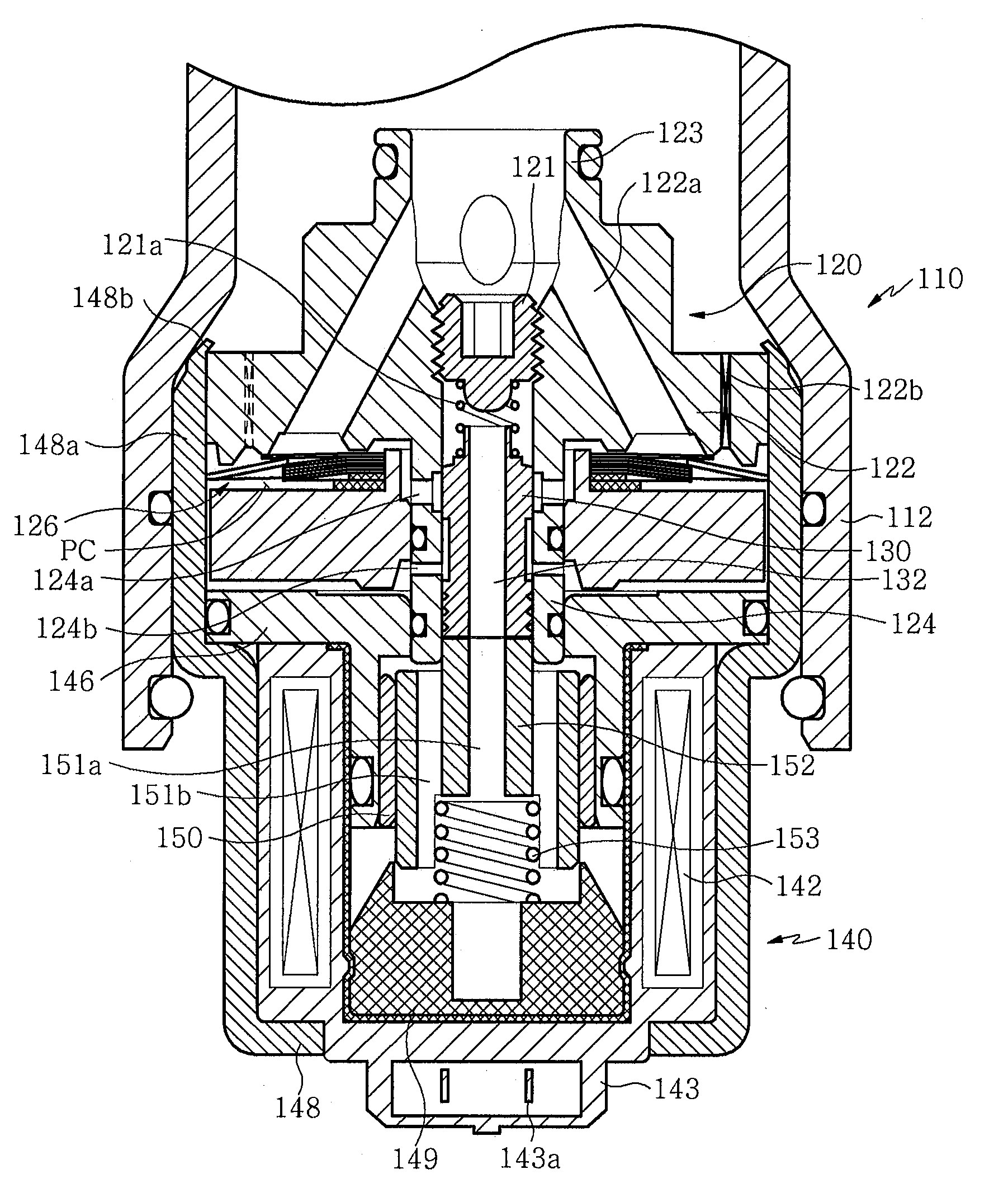
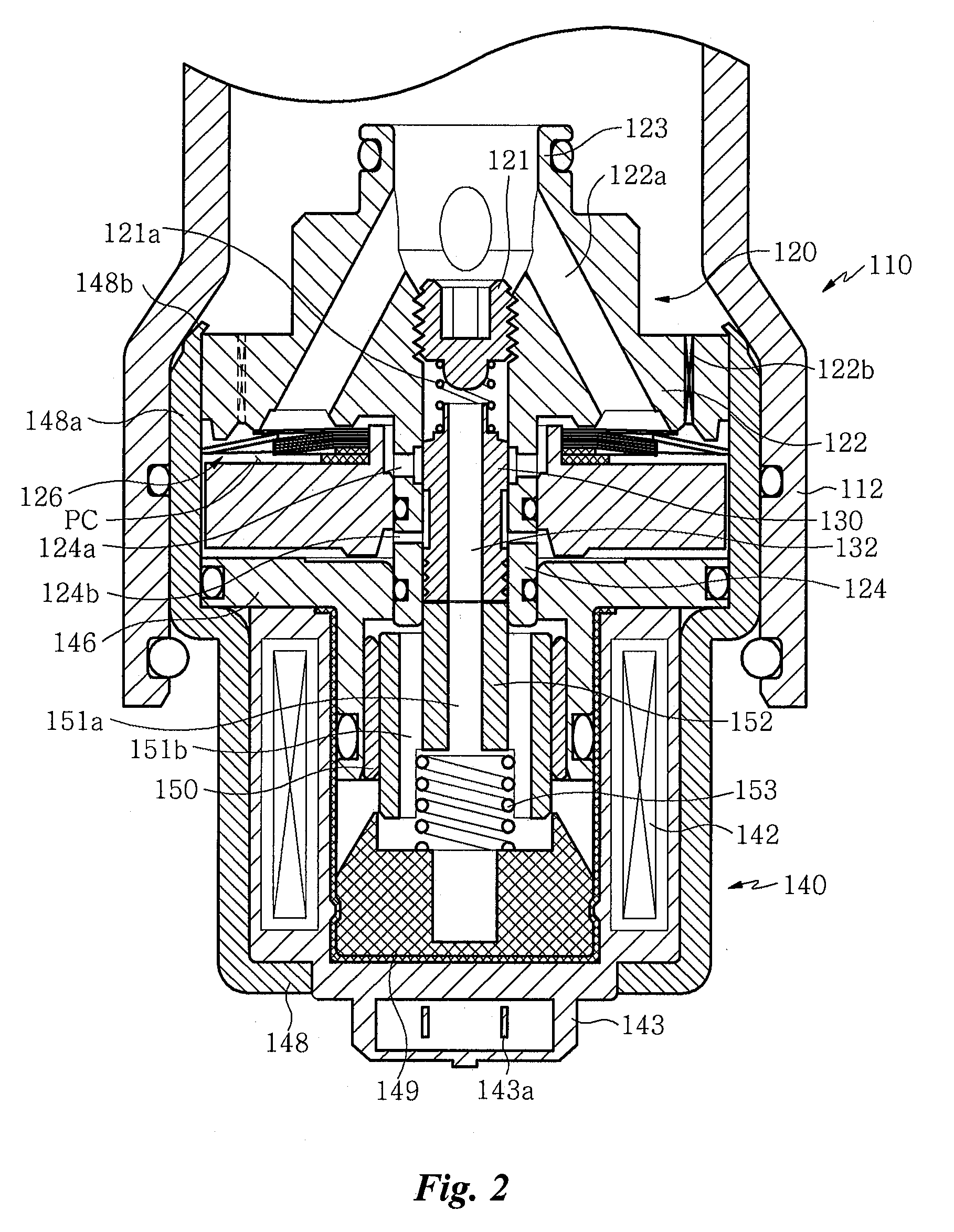
[0021]FIG. 2 is a sectional view of a damping force variable valve 10 according to one embodiment.

[0022]The damping force variable valve 110 includes a cylinder and a reservoir chamber communicating with the cylinder and can be installed in a shock absorber which is formed with a high pressure part connected to a rebound chamber of the cylinder and a low pressure part connected to the reservoir chamber.

[0023]Such a damping force variable valve 110 includes a retainer 120 installed in a valve housing 112 and a main disk 126, and a solenoid part 140 coupled to a lower side of the valve housing 112.

[0024]The retainer 120 includes a main body 122 and a spool rod part 124 which in one aspect can be formed integrally with the main body 122.

[0025]The main body 122 is connected to a high pressure part at a central portion thereof and is formed to have a portion with a larger outer diameter. To this end, in the retainer 120, a connecting port 123 is configured to be coupled to the high press...


PUM


Abstract

A damping force variable valve includes a retainer including a spool rod part having a hollow portion formed at a central portion thereof to allow a spool to be inserted in the hollow portion, a solenoid part coupled to a lower side of the retainer and having a bobbin provided therein, the bobbin having a coil wound therearound for allowing a pressurizing rod in contact with the spool to move when voltage is applied, and a connector for connecting to a power supply part formed integrally with the bobbin.

Description

BACKGROUND[0001]1. Technical Field[0002]The present disclosure relates to a damping force variable valve, and more particularly, to a damping force variable valve of a shock absorber, wherein a connector is provided on a power supply part of a solenoid part to make an assembling process easy and the automatization thereof possible.[0003]2. Description of the Related Art[0004]In general, a shock absorbing device is provided in a vehicle to absorb vibrations or shocks transmitted from a road surface to an axle of the vehicle when the vehicle is driven and thus to improve a ride comfort. As one of the shock absorbing devices, a shock absorber has been employed in a vehicle.[0005]This shock absorber lowers damping force when a vehicle is driven under a normal condition to absorb vibrations caused by irregularities of a road surface and to enhance the ride comfort. Also, when the vehicle is turned, accelerated, decelerated, and / or driven at high-speed, this shock absorber increases dampi...

Claims


Application Information

Patent Timeline
IPC IPC(8): F16K31/06
CPCF16F9/463F16F9/34
Inventor JEE, YOUNG WHANPARK, KYU SHIK
Owner HL MANDO CORP
Features
  • R&D
  • Intellectual Property
  • Life Sciences
  • Materials
  • Tech Scout
  • Unparalleled Data Quality
  • Higher Quality Content
  • 60% Fewer Hallucinations
Learn More