Medical mini-environment device

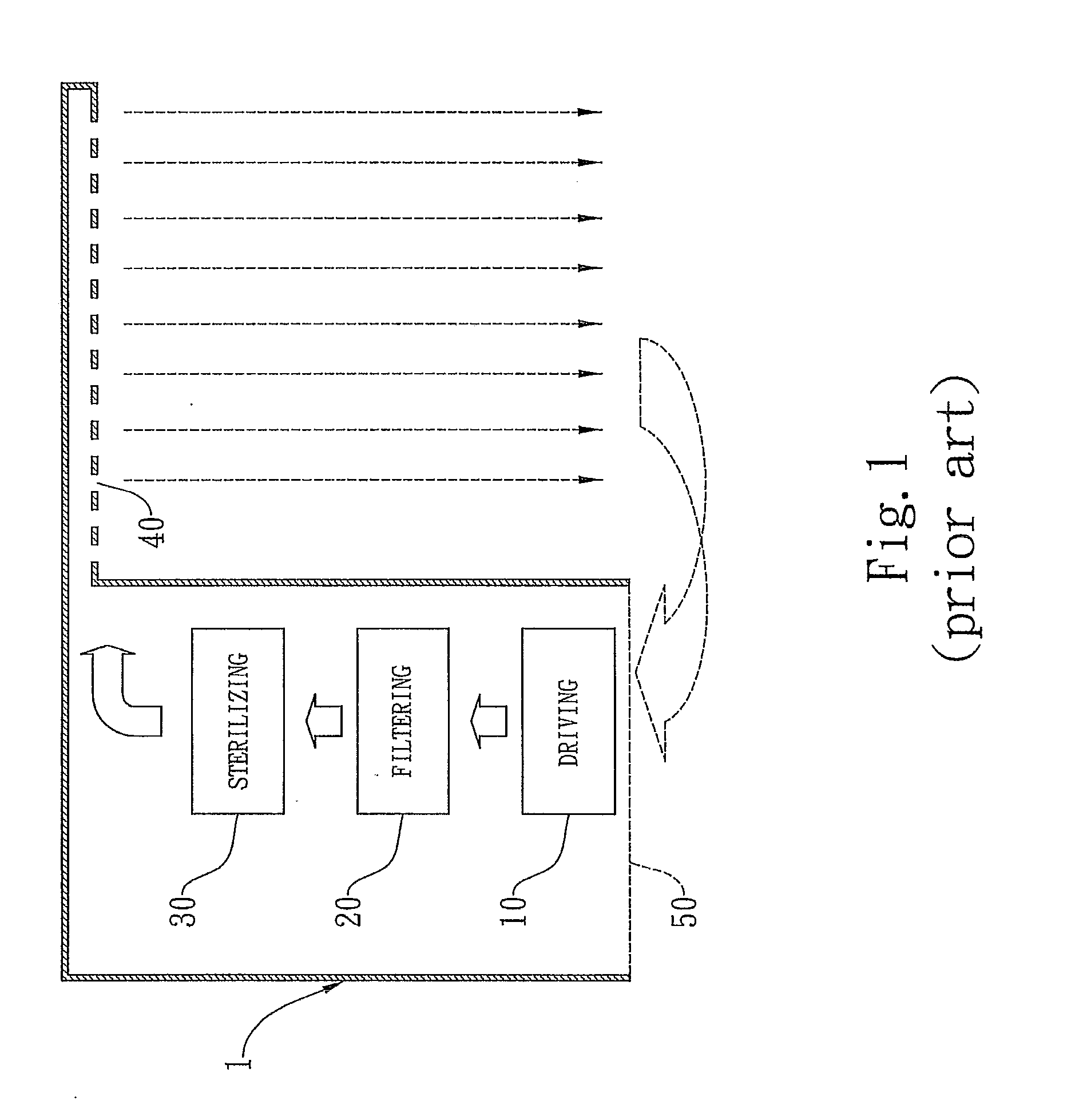
a medical environment and mini-environment technology, applied in ventilation systems, heating types, separation processes, etc., can solve the problems of high cost, unfavorable medical staff and people in those medical facilities, and generating a turbulent flow with a low-cleanliness, so as to ensure the air quality and cleanliness, clean and sterile medical environment, and eliminate germs in the air

Inactive Publication Date: 2010-01-07
IND TECH RES INST
View PDF14 Cites 5 Cited by
  • Summary
  • Abstract
  • Description
  • Claims
  • Application Information

AI Technical Summary

Benefits of technology

[0014]Accordingly, it is an object of the present invention to provide a ventilation apparatus for forming a sterile medical environment, in which a quasi-laminar downward air-flow pattern is introduced to ensure the cleanliness in a application region, in particular a sterile medical district. The ventilation apparatus of the present invention mainly includes a driving unit for circulating the air flow, a filtering unit for filtering dusts and pollutants in the air, a sterilizing unit for eliminating germs in the air so as to assure the air quality and cleanliness. By circulating clean air flow to a certain medical district, a clean and sterile medical environment can then be formed.

Problems solved by technology

Definitely, medical staffs and people in those medical facilities are jeopardous.
However, by replacing with a fan-filter unit (FFU) to overcome the foregoing problems, a huge expense and possible a space reconsideration are definitely inevitable.
These disadvantages include:1. generating a turbulent flow with a low-cleanliness which cannot effectively removes the pollutants;2. lacking control in direction of the pollutants flow; and3. unable to stabilize the air quality and cleanliness in a certain district.
Such a design is applicable for industry, e.g. general industrial, food industrial and dangerous industrial, but is not suitable for medical application.
This is because such apparatus fails to provide the patient with a uniform distribution of clean air, and the patient exposed to such atmosphere may feel uncomfortable.

Method used


Image

  • Medical mini-environment device
  • Medical mini-environment device
  • Medical mini-environment device

Examples


Embodiment Construction

[0022]The invention disclosed herein is directed to a ventilation apparatus for forming a clean air flow apply to sterile medical area. In the following description, numerous details are set forth in order to provide a thorough understanding of the present invention. It will be appreciated by one skilled in the art that variations of these specific details are possible while still achieving the results of the present invention. In other instance, well-known components are not described in detail in order not to unnecessarily obscure the present invention.

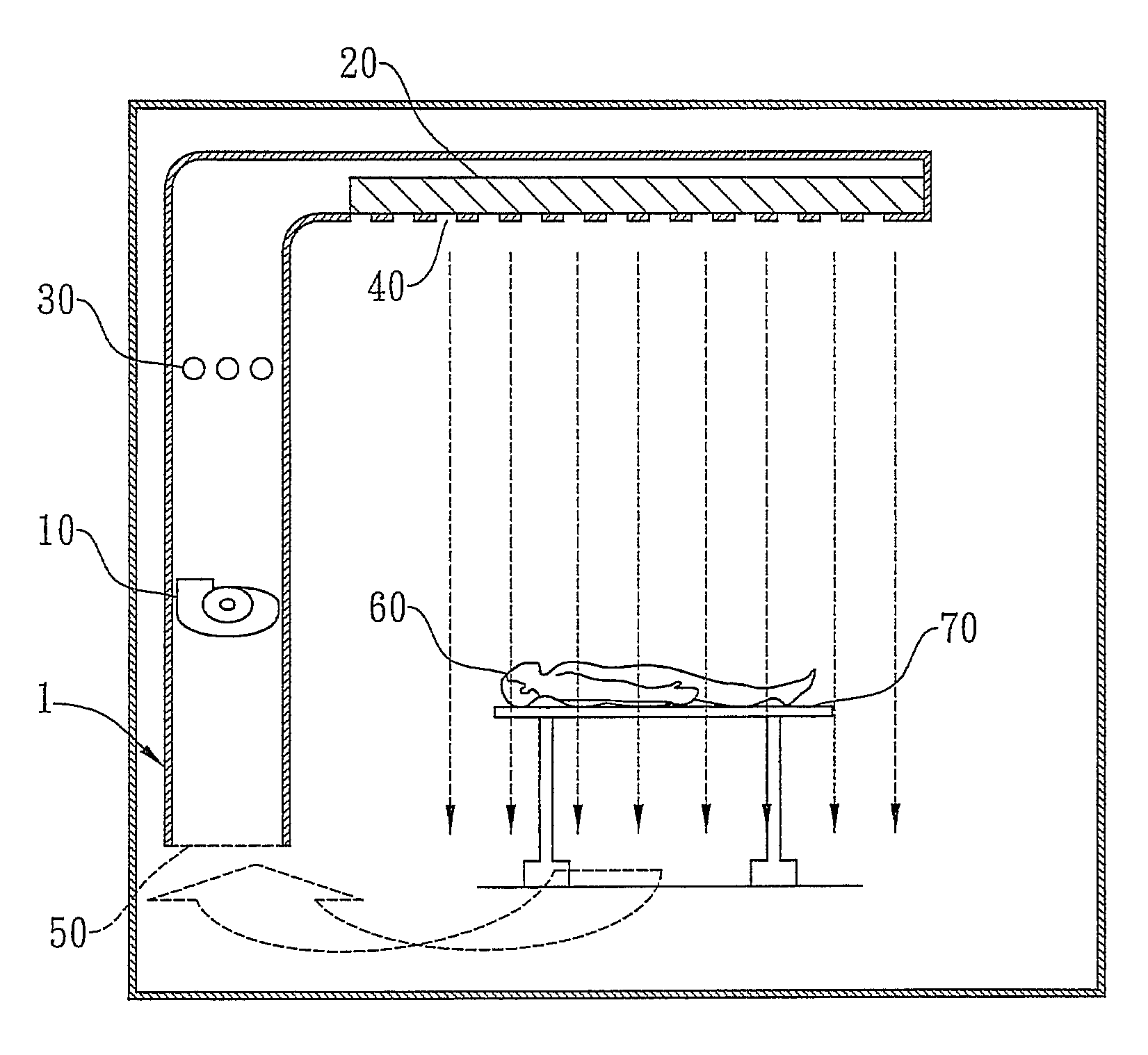
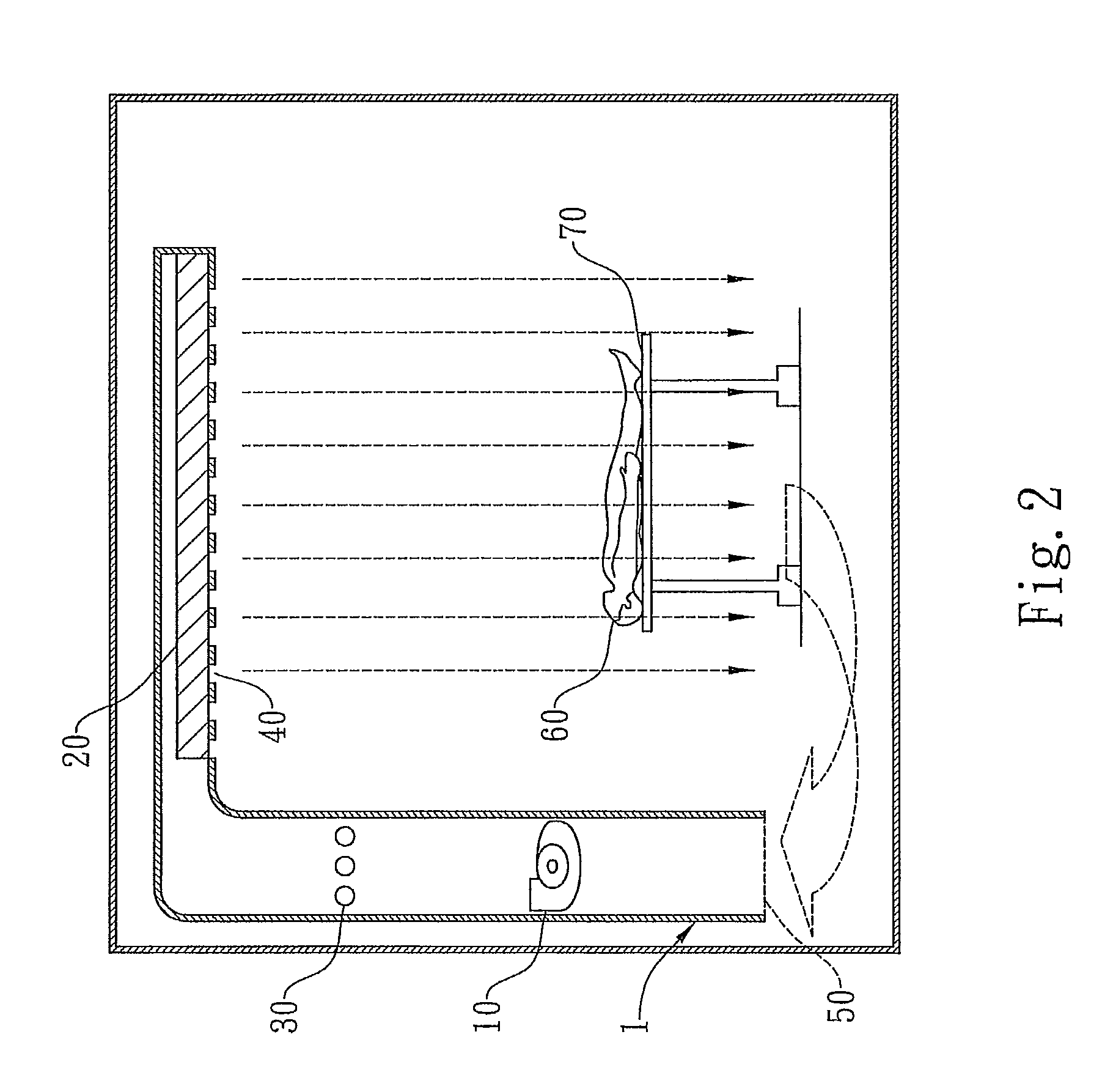
[0023]Referring now to FIG. 2, a schematic view of a preferred embodiment of the ventilation apparatus for forming a sterile medical area in accordance with the present invention is shown.

[0024]The ventilation apparatus 1 mainly includes an operation module and a transmission module integrated with the operation module but positioned oblique at a 90 degree. The operation module includes a driving unit 10 and a sterilizing unit 30. T...


PUM

PropertyMeasurementUnit
densitiesaaaaaaaaaa
volumeaaaaaaaaaa
relative humidityaaaaaaaaaa

Abstract

A ventilation apparatus for forming a sterile medical area mainly includes an operation module for ventilating the air. The apparatus for ensuring the air cleanliness includes a filtering unit for filtering dusts and particles in the air and a sterilizing unit for eliminating micro organisms. The clean and sterilized air is sent into the medical area via an air outlet to form a quasi-laminar air flow pattern. By application of the ventilation apparatus, the cleanliness of the medical area can be ensured.

Description

CROSS REFERENCES TO THE RELATED APPLICATIONS[0001]This is a Continuation-in-part of U.S. application Ser. No. 11 / 303,933, filed Dec. 19, 2005, now pending.BACKGROUND OF THE INVENTION[0002](1) Field of the Invention[0003]The invention relates to an interior ventilation apparatus, and more particularly to a local ventilation apparatus that serves in a medical facility, in which the ventilated air is formed as a controlled air flow region to shield a limited sterile medical environment.[0004](2) Description of the Prior Art[0005]In the midst of various micro pollutants in the atmosphere, quality of the surrounding air is paid more attention by people who care about their health. As well known, various diseases such as the pulmonary tuberculosis, the sever acute respiratory syndrome (SARS), the flu and some respiratory illness can be spread by the air, especially droplet nuclei and suspension aerosols. Such an understanding draws particular alert in medical facilities where always gathe...

Claims


Application Information

Patent Timeline
Patent Type & Authority Applications(United States)
IPC IPC(8): F24F7/007
CPCB01D46/0028B01D46/10F24F2003/1667B01D2279/65F24F3/1607B01D2279/51F24F3/163F24F8/22Y02A50/20
Inventor JENG, MING-SHANLEE, YAN-CHINGCHOU, YA-WENLAN, CHAO-HO
Owner IND TECH RES INST
Why Eureka
Try Eureka