
Limited Motion Prosthetic Intervertebral Disc

a prosthetic disc and limited motion technology, applied in the field of limited motion prosthetic discs and intervertebral prosthetic discs, can solve the problems of back pain, degeneration and/or dysfunction of one or more intervertebral discs, and affecting the health and productivity of people around the world

Active Publication Date: 2010-01-07
SIMPLIFY MEDICAL PTY LTD
View PDF115 Cites 125 Cited by
  • Summary
  • Abstract
  • Description
  • Claims
  • Application Information

AI Technical Summary

Problems solved by technology

Back pain takes an enormous toll on the health and productivity of people around the world.
One common cause of back pain is injury, degeneration and / or dysfunction of one or more intervertebral discs.
Discs often become damaged due to wear and tear or acute injury.
Degeneration or other damage to a disc may cause a loss of “disc height,” meaning that the natural space between two vertebrae decreases.
Decreased disc height may cause a disc to bulge, facet loads to increase, two vertebrae to rub together in an unnatural way and / or increased pressure on certain parts of the vertebrae and / or nerve roots, thus causing pain.
In general, chronic and acute damage to intervertebral discs is a common source of back related pain and loss of mobility.
When one or more damaged intervertebral discs cause a patient pain and discomfort, surgery is often required.
Although existing disc prostheses provide advantages over traditional treatment methods, many patients are not candidates for any of these artificial discs due to facet degeneration, instability, poor bone strength, previous surgery, multi-level disease, and pain sources that are non-discogenic.

Method used


Image

  • Limited Motion Prosthetic Intervertebral Disc
  • Limited Motion Prosthetic Intervertebral Disc
  • Limited Motion Prosthetic Intervertebral Disc

Examples


Embodiment Construction

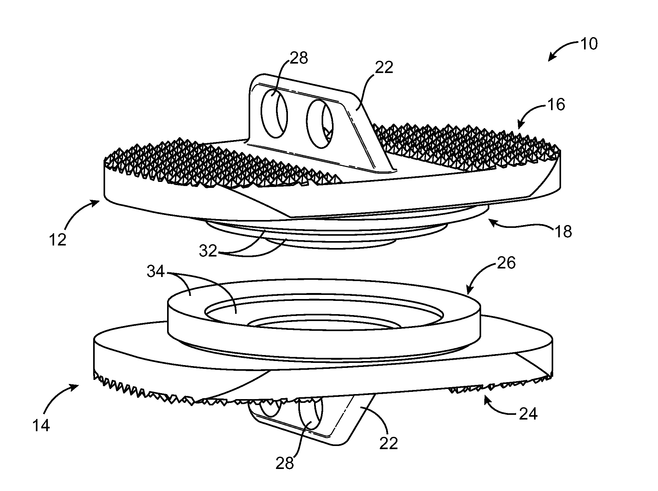
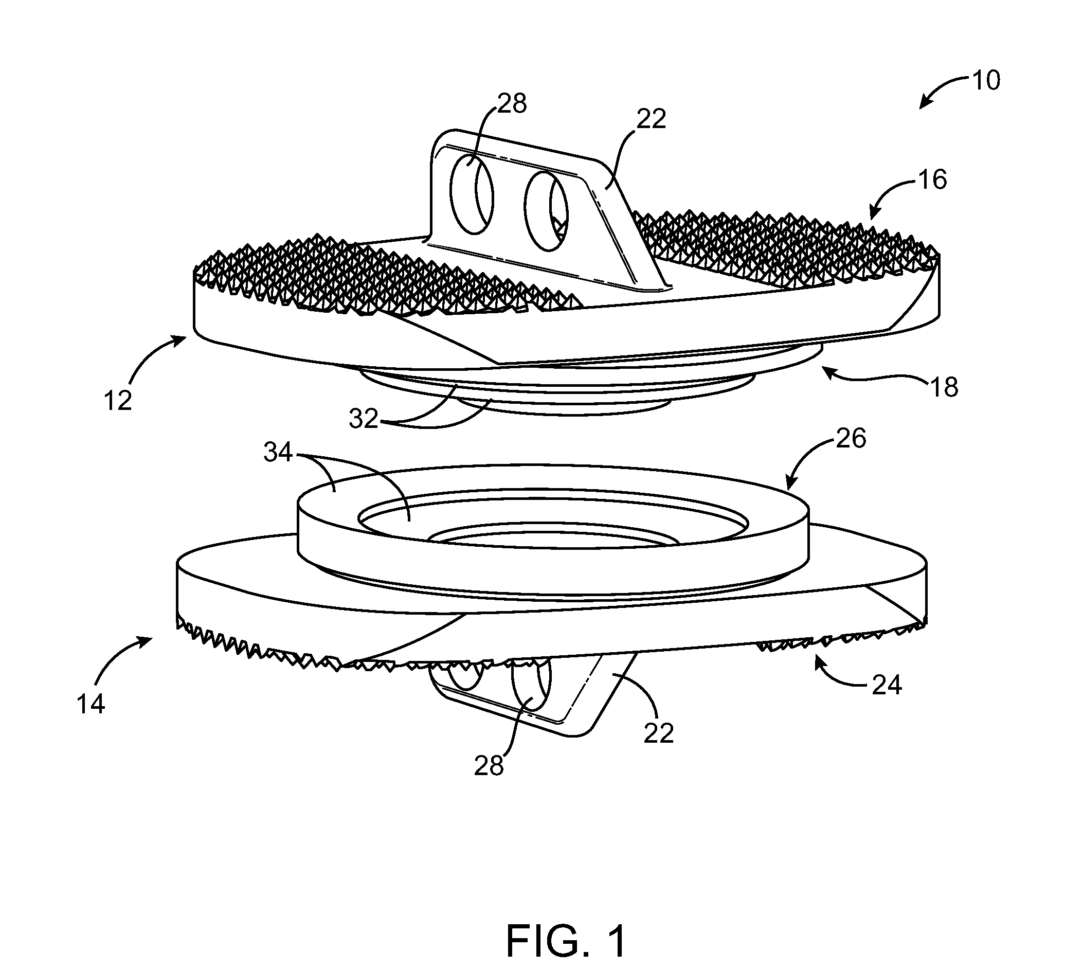
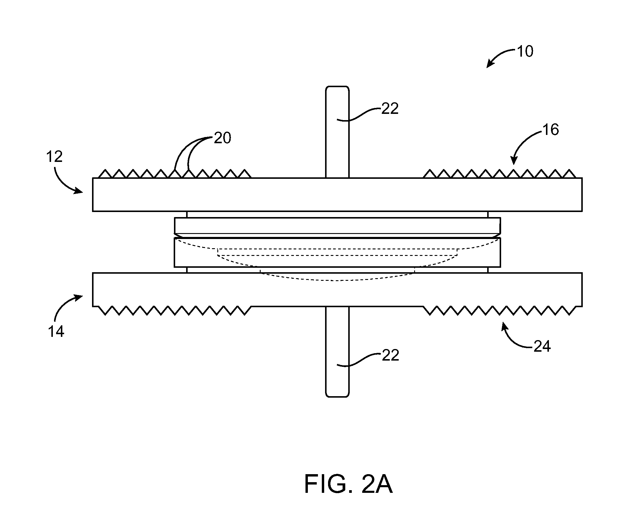
[0019]A prosthetic intervertebral disc 10 shown in FIG. 1 includes an upper plate 12 and a lower plate 14 and employs congruent stepped features to provide limited motion between the plates. The stepped features can be used to provide articulating motion of a rocking type rather than a rubbing or translating type of motion provided in many artificial discs. The stepped features can be designed to restrict motion in flexion-extension or lateral bending to less than a predetermined angle. The stepped design can be modified to either allow or prevent rotational motion between the plates 12, 14 as will be described in detail below. The limited motion disc, as shown in FIG. 1 substantially prevents translation, however some limited translation can be provided by modification of the relative sizes of the stepped features.

[0020]The limited motion disc 10 allows the surgeon an alternative to the extremes of no motion provided by fusion procedures and the typical 10-20 degrees of motion in e...


PUM

PropertyMeasurementUnit
Lengthaaaaaaaaaa
Angleaaaaaaaaaa
Angleaaaaaaaaaa

Abstract

A prosthetic intervertebral disc includes an upper plate and a lower plate and employs congruent stepped features to provide limited articulating motion between the plates. The stepped features can be used to provide articulating motion of a rocking type rather than a rubbing or translating type of motion provided in many artificial discs. Each of two parts of the intervertebral disc includes two or more stepped bearing surfaces, having curved or flat shapes, which mate with one another to provide the articulation to the disc. The stepped features can be designed to restrict motion in flexion-extension or lateral bending to less than a predetermined angle. The stepped design can be modified to either allow or prevent rotational motion between the plates. The limited motion disc substantially prevents translation, however some limited translation can be provided by modification of the relative sizes of the stepped features.

Description

CROSS-REFERENCES TO RELATED APPLICATIONS[0001]This application claims priority to U.S. Provisional Application No. 61 / 077,806, filed Jul. 2, 2008, entitled “LIMITED MOTION PROSTHETIC INTERVERTEBRAL DISC,” the full disclosure of which is incorporated herein by reference.BACKGROUND OF THE INVENTION[0002]The present invention relates to medical devices and methods. More specifically, the invention relates to intervertebral prosthetic discs and methods of preserving limited motion upon removal of an intervertebral disc.[0003]Back pain takes an enormous toll on the health and productivity of people around the world. According to the American Academy of Orthopedic Surgeons, approximately 80 percent of Americans will experience back pain at some time in their life. In the year 2000, approximately 26 million visits were made to physicians' offices due to back problems in the United States. On any one day, it is estimated that 5% of the working population in America is disabled by back pain....

Claims


Application Information

Patent Timeline
IPC IPC(8): A61F2/44
CPCA61F2/4425A61F2310/0088A61F2002/30652A61F2002/30655A61F2002/30662A61F2002/30665A61F2002/30843A61F2002/30884A61F2002/30899A61F2250/0098A61F2310/00017A61F2310/00023A61F2310/00407A61F2310/00796A61F2002/3008
Inventor ARRAMON, YVES
Owner SIMPLIFY MEDICAL PTY LTD
Learn More