
System for Automatically Detecting Power System Configuration

a technology of automatic detection and power system, applied in the direction of electrical apparatus construction details, powerline communications applications, instruments, etc., can solve the problems of high voltage device cost, feeder meter design and construction, and theft directly from high voltage feeders

Active Publication Date: 2010-01-14
GRID2020
View PDF10 Cites 85 Cited by
  • Summary
  • Abstract
  • Description
  • Claims
  • Application Information

AI Technical Summary

Problems solved by technology

Theft directly from a high voltage feeder can be done by the unauthorized installation of a non-utility owned distribution transformer on the feeder.
The utility would not necessarily know about the existence of such a transformer and thus a comparison between energy supplied by the utility owned distribution transformers and the energy consumed by the end-users would not detect this kind of electricity theft.
A major disadvantage of this approach is that the feeder meter must be designed and built for high voltage operation.
High voltage devices are expensive and depending on the design, can be hazardous to install.
Furthermore, voltage drops occur in every feeder due to current flow and line resistance, and these voltage drops are a source of measurement error in the comparison.
This is an expensive labour intensive process, and often these maps are not kept up-to-date.

Method used


Image

  • System for Automatically Detecting Power System Configuration
  • System for Automatically Detecting Power System Configuration
  • System for Automatically Detecting Power System Configuration

Examples


Embodiment Construction

[0015]Energy accounting as a method of detecting electricity theft can be very effective at the distribution transformer level because of the small number of customers involved. Errors due to line losses may be 0.5% to 3% and the number of customers may be no more than ten. In this case the total amount of energy lost to the lines would amount to no more than a fraction of the amount used by a single customer, and an even smaller fraction of the amount likely to be involved in any theft.

[0016]At the feeder level, the situation is different because many more customers are involved. Here the energy lost in the lines is likely to be many times greater than the amount used by a single customer. Thus, the detection of theft is more difficult, and the sensitivity and reliability of the method is heavily dependent on the accuracy of the energy accounting process.

[0017]An improvement in the accuracy of the energy accounting process can be achieved by estimating the line losses and compensat...


PUM


Abstract

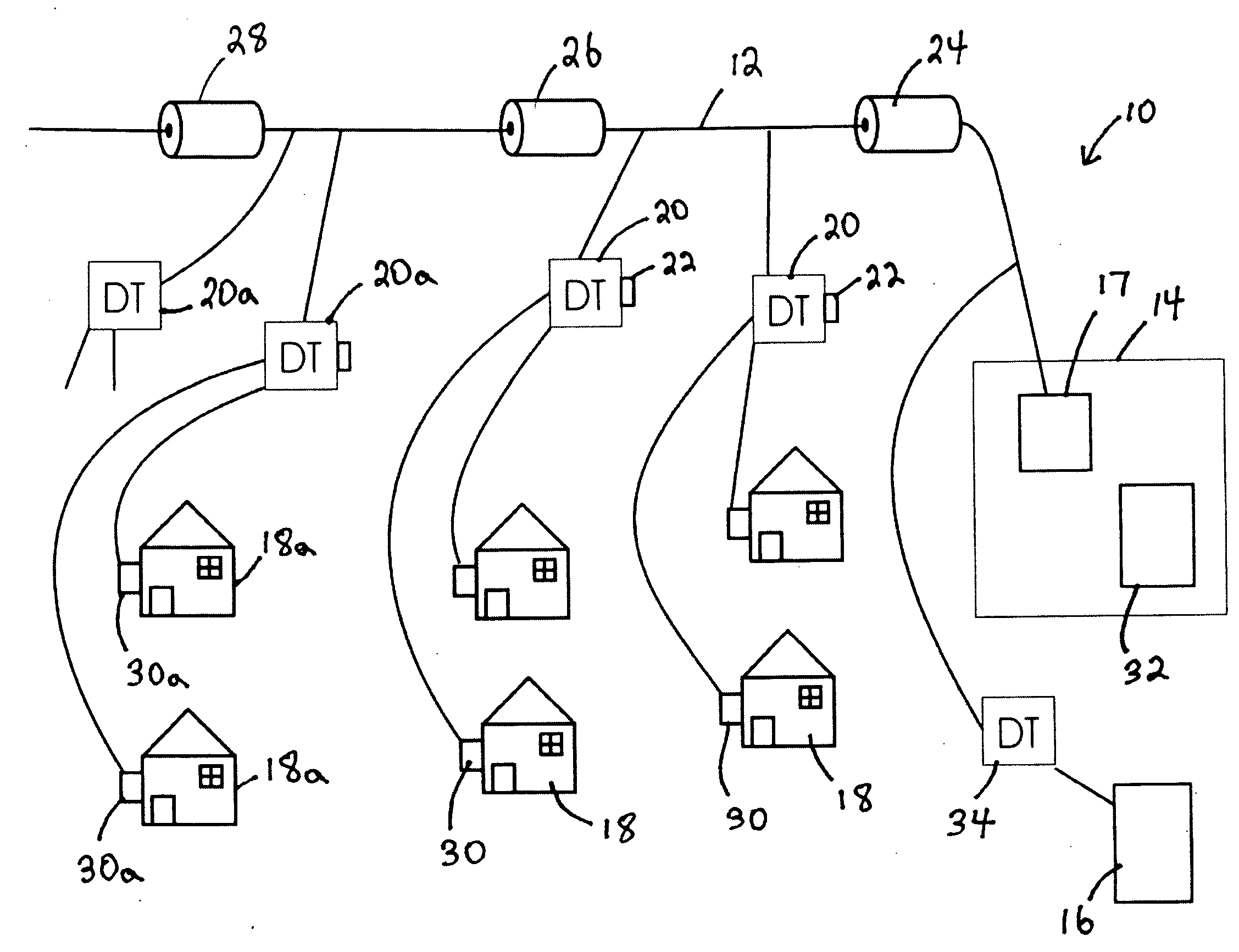
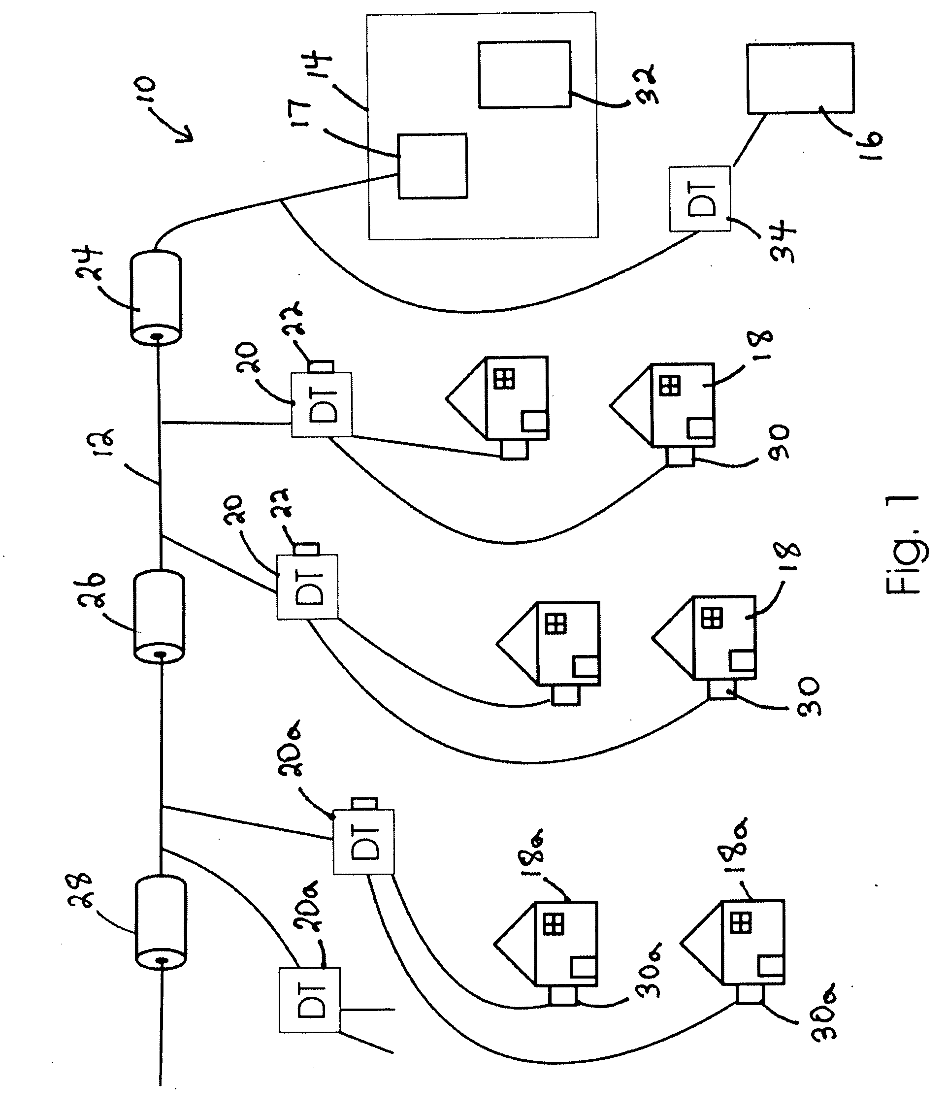
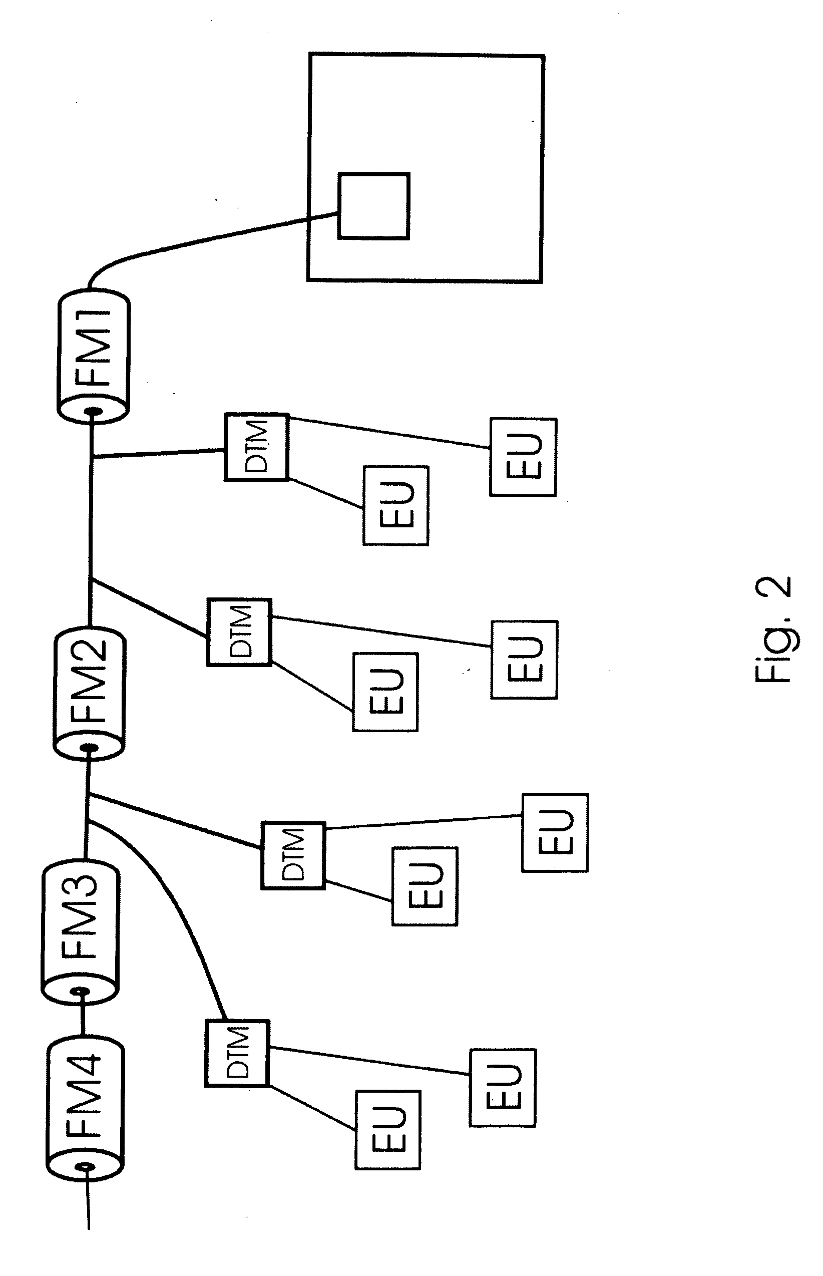
There is disclosed a method of detecting the configuration of a network having a feeder line with a plurality of feeder meters and distribution transformer meters (DTMs) coupled thereto and with one or more customer meters and / or customer configuration modules coupled to the distribution transformers. The method includes the steps of having each of the feeder meters transmit a uniquely identifiable signal through the feeder line. The DTMs then identifying the phase of each of the uniquely identifiable signals and then transmitting the phase of each of the uniquely identifiable signals to a data collector along with a unique DTM identifier. The connectivity relationship between the feeder meters and distribution transformer meters is then extrapolated by comparing the phase information transmitted by the DTMs. The relationship of the customer meters relative to the DTMs can also be plotted by having each DTM transmit the DTM identifier to all of their respective customer meters, who then transmit this to the data collector along with their customer meter identifier. The method also permits the determination of which phase the DTM is connected to by analyzing the phase angle of a demodulated feeder meter signal.

Description

CROSS REFERENCE TO RELATED APPLICATION[0001]This application is a continuation in part of U.S. patent application Ser. No. 12 / 172,112 filed Jul. 11, 2008, the entirety of which is incorporated herein by reference.FIELD OF THE INVENTION[0002]The invention relates generally to methods for automatically detecting the configuration of an electricity network.BACKGROUND OF THE INVENTION[0003]With rising energy prices, concerns about the environment, and an increased emphasis on energy conservation, there has been an increased interest in the detection and prevention of electricity theft. Theft directly from a high voltage feeder can be done by the unauthorized installation of a non-utility owned distribution transformer on the feeder. The utility would not necessarily know about the existence of such a transformer and thus a comparison between energy supplied by the utility owned distribution transformers and the energy consumed by the end-users would not detect this kind of electricity t...

Claims


Application Information

Patent Timeline
Patent Type & Authority Applications(United States)
IPC IPC(8): H02J4/00
CPCG01R15/18H04B2203/5433H04B3/546G01R22/06
Inventor DE BUDA, ERIC GEORGEKUURSTRA, JOHN CECIL
Owner GRID2020
Learn More