Current sensing lug

a current sensing and lug technology, applied in the direction of transmission systems, instruments, sustainable buildings, etc., can solve the problems of heightened security issues with consumers and utilities, personnel and staffing costs of meter reading crews, and practicable limitations on how efficiently this procedure can actually be performed

Inactive Publication Date: 2006-05-18
CENTERPOINT ENERGY
View PDF15 Cites 47 Cited by
  • Summary
  • Abstract
  • Description
  • Claims
  • Application Information

AI Technical Summary

Benefits of technology

[0009] Briefly, the present invention provides a new and improved current sensing lug to connect electrical power service from a power distribution system to a customer site and measure energy usage by the customer site. The current sensing lug according to the present invention has a connector terminal which is adapted to be connected to the power distribution system and a connector barrel adapted to be connected by a service conductor to the customer site. A lug body mounted between the connector terminal and the conductor barrel permits the flow of electrical power to the service conductor. An electrical current sensor of the lug obtains data indicating the amount of energy provided from the connector terminal to the service conductor.

Problems solved by technology

However, there are practical limitations on how efficiently this procedure can actually be performed.
Personnel and staffing costs of meter reading crews became a concern as the numbers of users increased.
Also, since security is a major concern of most homeowners today, access to the actual location of the consumer's meters has heightened security issues with consumer and utilities.
This directly and adversely impacted the accuracy and efficiency of the self-reporting process.
Collection of meter data was a labor intensive and costly process.
However, electromechanical metering devices generally had little or no communication capability.
However, for AMR applications, electric utilities were still dependent on a meter device coupled with the service entrance on a home, apartment or business.
This process has still not been widely used by most utilities because it is cost prohibitive in its adaptation and had mainly a limited, one-way communication, that of reporting usage read from a meter to some data processing center or site for processing and billing.

Method used


Image

  • Current sensing lug
  • Current sensing lug
  • Current sensing lug

Examples


Embodiment Construction

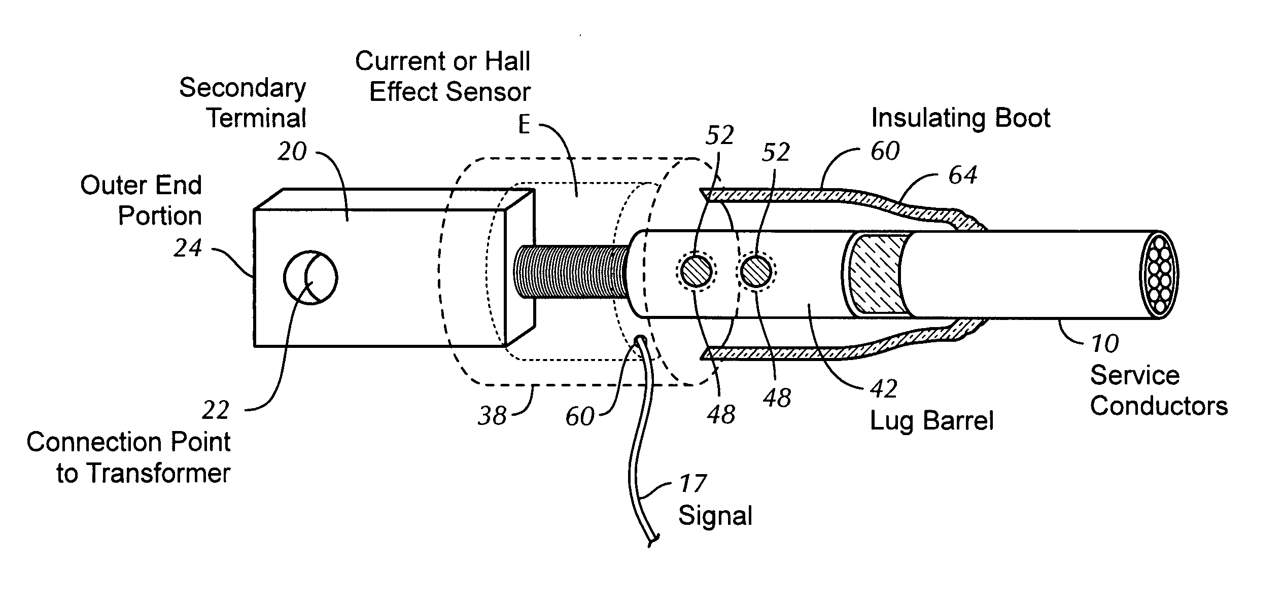
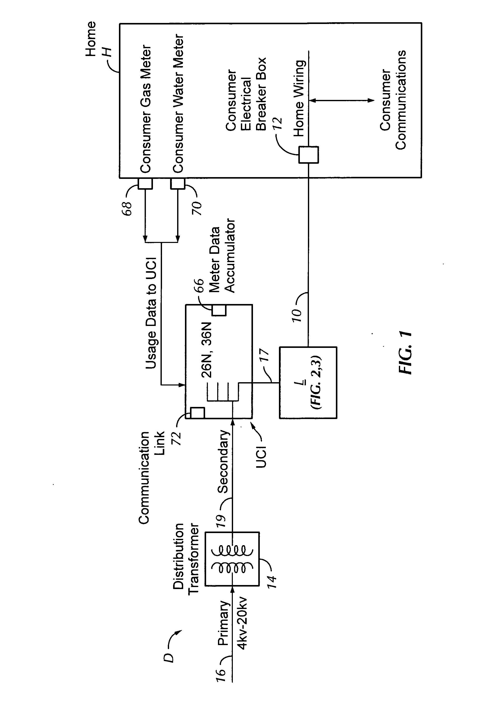
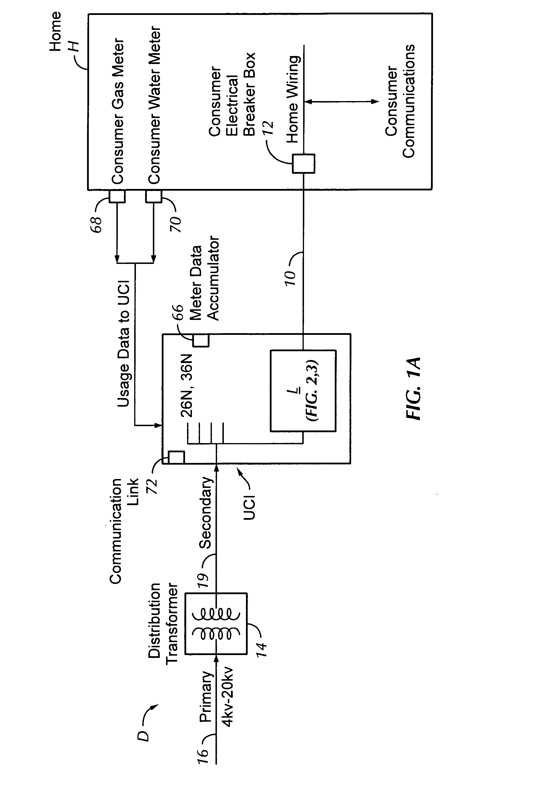
[0017] In the drawings, the letter L designates generally a current sensing lug according to the present invention which is provided as a component unit of a power distribution arrangement D (FIGS. 1 and 1A; 2 and 2A) to provide electrical power service to one or more customer sites H. Individual power distribution and connecting lugs L according to the present invention connect individual sites H to the distribution arrangement D and sense the amount of energy used by the site to which they are connected. The example customer site receiving power in FIG. 1 is shown as a home H. It should be understood that the sites connected by lugs L receiving power from the power distribution arrangement D may be buildings, factories, apartments or any other facilities or location receiving electrical power for consumption. Accordingly, the owner or occupants of such sites or other recipients of the electrical power being distributed for energy usage purposes are referred to as customers or user...


PUM


Abstract

Electrical current in an electrical power distribution system, such as at a power distribution transformer or the like, for an electrical utility is transferred through a current sensing connector lug mounted with an end of a user or consumer's service connection conductor or line. The lug is connectable to the power distribution transformer or secondary conductor, for connecting the user's service conductor to power from the distribution system. The flow of electrical current and thus the amount of electric power provided to an individual user is measured at the current sensing lug rather than at the user's site or facility, removing the need for watt-hour meters at the user or customer site, and also thus removing the requirement for conventional meter reading crews or for automated meter reading equipment. The current sensing lug also facilitates the accumulation of other utility data information, which formerly required a site visit by utility personnel.

Description

REFERENCE TO RELATED APPLICATIONS [0001] This application claims the benefit of U.S. Provisional Patent Application Ser. No. 60 / 624,023, filed Nov. 1, 2004.BACKGROUND OF THE INVENTION [0002] 1. Field of the Invention [0003] The present invention relates to sensing the amount of current flow in connection with metering or measuring of electrical energy usage for collection and communication of electrical energy usage data. [0004] 2. Description of the Related Art [0005] So far as is known, the most common method for determining the amount of electricity delivered to a consumer has been to read an electric utility meter (usually measuring kilowatt hours), which was mounted on the home or building of the consumer being served. This arrangement was also usually comparable for both gas and water meters as well, with separate usage meters for each of the commodities provided by those utilities being located on or near the building or property being served. Service charges for those commod...

Claims


Application Information

Patent Timeline
Patent Type & Authority Applications(United States)
IPC IPC(8): G01R19/00G06F19/00
CPCG01D4/002G01R1/203G01R15/18G01R15/205G01R21/133G01R22/00G01R22/065Y02B90/241Y04S20/32Y04S20/30Y02B90/20
Inventor BORKOWSKI, TIMOTHY J.GRASSHOFF, RICHARD L.MURPHY, R. KENNETHCORTEZ, DONATO
Owner CENTERPOINT ENERGY
Why Eureka
Try Eureka