Power line communications spread spectrum symbol timing and random phasing

a power line communication and random phasing technology, applied in the field of electronic signal modulation, can solve the problems of non-linear phase shift, cumbersome and time-consuming, and existing modulation techniques that cannot be easily implemented or reliably performed in the high-noise environment of a power lin

Inactive Publication Date: 2000-08-08
GENERAL ELECTRIC CO
View PDF6 Cites 49 Cited by
  • Summary
  • Abstract
  • Description
  • Claims
  • Application Information

AI Technical Summary

Problems solved by technology

This can be cumbersome and time consuming when there are many customers, especially if they are dispersed over a large geographic area.
The power wires connected to each customer's power meter constitute a possible path for communicating with the power meters; however, existing modulation techniques may not be easily implemented or reliably perform in the high-noise environment of a power line.
Moreover, transformers employed in the power line network are inherently inductively coupled and consequently introduce non-linear phase shifts in signals passing through the transformer.
Therefore, complex communications systems are required to perform reliably in the high-noise, phase distorted power line channels.

Method used


Image

  • Power line communications spread spectrum symbol timing and random phasing
  • Power line communications spread spectrum symbol timing and random phasing
  • Power line communications spread spectrum symbol timing and random phasing

Examples


Embodiment Construction

Basic GHM

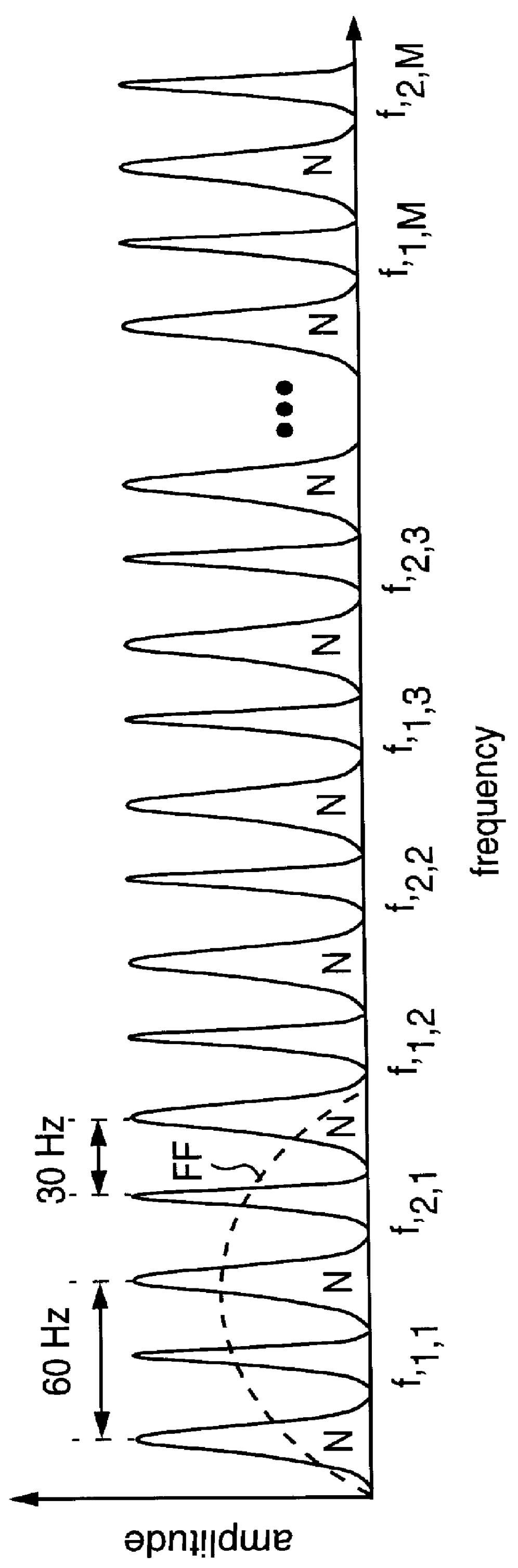
Geometric Harmonic Modulation (GHM) for communications systems has been described for radiowave communication in Hershey et al. U.S. Pat. No. 5,519,725 issued May 21, 1996, assigned to the instant assignee, and which is incorporated herein by reference. GHM allocates signaling energy into lobes, or tones, at different frequencies evenly spaced at geometrically increasing multiples of a base frequency. The GHM signaling waveforms {W.sub.n (.PHI.,R;t)} are true spread spectrum signals in that the signal bandwidth, i.e., the bandwidth from the lowest frequency tone to the highest, vastly exceeds the information bandwidth conveyed by the GHM transmission.

Binary GHM signals convey binary data by inverting or not inverting the GHM waveform {W.sub.n (.PHI.,R;t)} during a bit duration interval.

It is not necessary for the GHM transmitter and the GHM receiver to "agree" on the best frequency on which to send data, as the same data is sent on each of the GHM tones which are spread thr...


PUM


Abstract

A system for spread spectrum power line communications employs a harmonic modulation (HM) transmitter coupled to the power line for transmitting message bits to an HM receiver. The spread spectrum accommodates a plurality of HM transmitters simultaneously occupying the same bandwidth. The spectrum of HM, in a frequency range above 60 Hz but below the maximum frequency that will carry through a distribution transformer, is ideal in combating carrier synchronous noise since it can be interleaved with the noise harmonics and therefore be effectively spectrally disjoint with the synchronous noise process spectrum.

Description

1. Field of the InventionThis invention generally relates to electronic signal modulation and, more particularly, to spread spectrum symbol timing in Harmonic Modulation (HM) power line communications (PLC).2. Background DescriptionElectric power companies typically have a service person visit customers and read a power meter to determine the amount of power consumed for billing purposes. This can be cumbersome and time consuming when there are many customers, especially if they are dispersed over a large geographic area.It would be beneficial for power companies to read these electric power meters remotely. The power wires connected to each customer's power meter constitute a possible path for communicating with the power meters; however, existing modulation techniques may not be easily implemented or reliably perform in the high-noise environment of a power line. Moreover, transformers employed in the power line network are inherently inductively coupled and consequently introduce...

Claims


Application Information

Patent Timeline
Patent Type & Authority Patents(United States)
IPC IPC(8): H04B1/69H04B3/54
CPCH04B1/69H04B3/54H04B2203/5416
Inventor HERSHEY, JOHN ERIKSAULNIER, GARY JUDEKORKOSZ, RICHARD AUGUSTWELLES, II, KENNETH BRAKELEYGAUS, JR., RICHARD CHARLES
Owner GENERAL ELECTRIC CO
Why Eureka
Try Eureka