System for Determining Objects

a technology of objects and systems, applied in the field of multimodal detection of objects, can solve the problems of system-related, application-specific restrictions, adverse effects on the detection of objects, etc., and achieve the effect of simple, robust, reliable braking strategies

Inactive Publication Date: 2010-01-14
CONTINENTAL TEVES AG & CO OHG +1
View PDF21 Cites 44 Cited by
  • Summary
  • Abstract
  • Description
  • Claims
  • Application Information

AI Technical Summary

Benefits of technology

[0017]The invention makes available a simple, robust system for differentiating objects in the surroundings of a vehicle in order to derive reliable braking strategies on this basis.
[0021]It is particularly advantageous that the system minimizes the data flow between the two sensors by preselecting relevant objects in the radar. The relatively small quantity of data to be evaluated considerably increases the computing speed for determining relevant objects.
[0024]This solution has the advantage that the invention involves target confirmation since the acquired data from the surroundings detection means are checked, verified and confirmed in order to permit the sensors to supplement one another, as result of which the transmission of data between the sensors can easily be implemented and it is not necessary to place any stringent technical requirements on the systems.
[0025]The invention involves target confirmation since the acquired data from the surroundings detection means are checked, verified and confirmed in order to permit the sensors to supplement one another, in which context the transmission or exchange of data between the sensors can easily be implemented and the systems do not have to meet any complex technical requirements.
[0026]In one advantageous refinement of the invention, the carriageway markings are used for improved situation analysis.

Problems solved by technology

However, the potential of such systems cannot be used entirely unless all the subsystems have information about the driving state, the surroundings of the vehicle and the driver himself.
Furthermore, it proves disadvantageous that the LIDAR sensors which are suitable for relatively large measuring ranges lose local resolution as the distance from an object increases, which has an adverse effect on the detection of objects.
In spite of the very high efficiency of the systems, system-related, application-specific restrictions arise:
This situation analysis cannot serve as a basis for initiating any strong autonomous braking processes, owing to the high level of uncertainty.
Furthermore, the range of the sensor is always limited in the surroundings by vehicles or objects, and the coefficient of friction which is highly important for the engagement strategy and warning strategy is not known from the outset.

Method used


Image

  • System for Determining Objects
  • System for Determining Objects
  • System for Determining Objects

Examples


Embodiment Construction

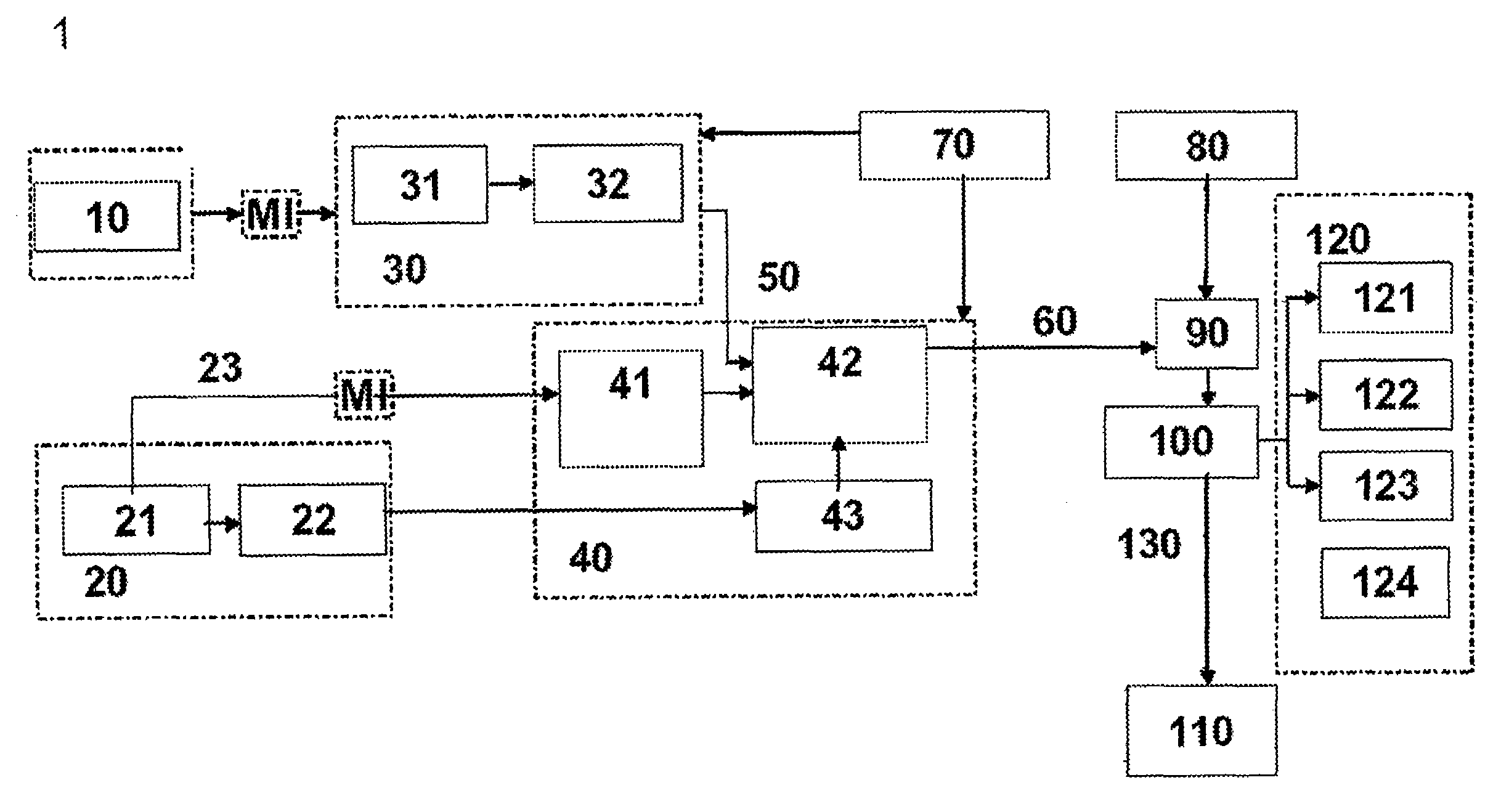
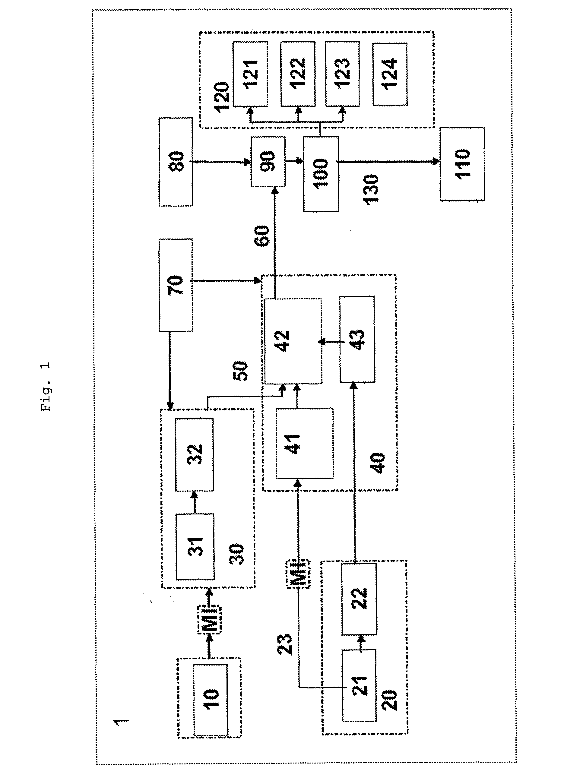
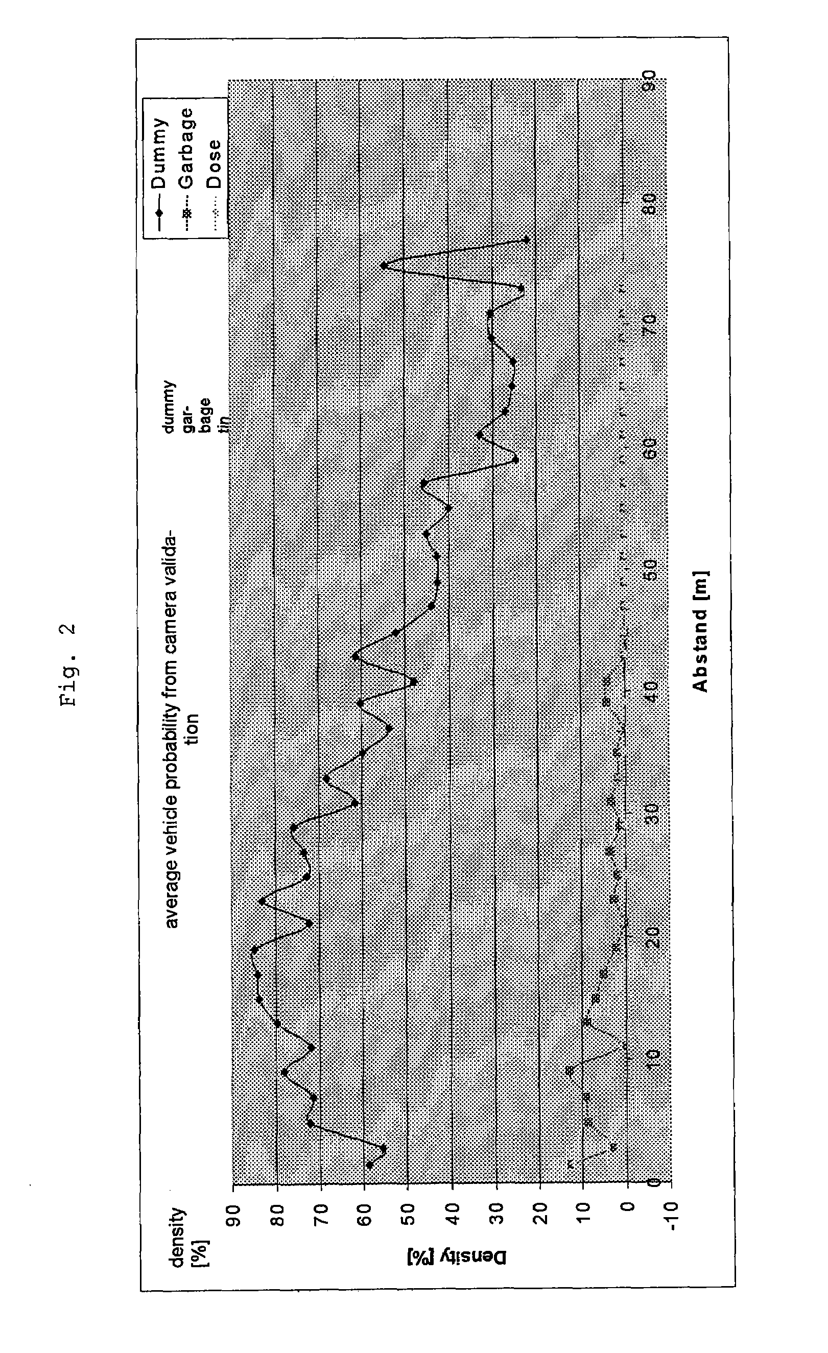
[0031]As is illustrated in FIG. 1, the radar sensor 10 initially carries out a preselection of relevant targets or objects 60. The position of these objects is signalled directly, or as is shown in FIG. 1, signalled indirectly to the camera via an object-determination means and a situation analysis means 42. If the camera can classify an object as relevant in a specific region, this is accepted as a relevant target or object. The principle during detection is to search for various optical characteristics of a vehicle at the position determined in the field of vision by the radar 10, at which position a target has been detected by the radar 10. Depending on whether a large number of characteristics or only a small number of characteristics have been detected, the detection rate increases, and therefore the probability increases that the detected object is, for example, a vehicle.

[0032]By using a radar close-range sensor system (24 GHz radar) 10, it is possible not only to implement c...


PUM


Abstract

A system for multimodal detection of objects in a field of vision located in front of or behind a vehicle, wherein a surroundings-sensing process is carried out by a radar sensor, the radar sensor output signal is fed to a radar signal analysis method, and a visual surroundings-sensing process is carried out by a video sensor, the video output signal being fed to a video analysis method. Object determination takes place such that objects detected by the radar signal analysis method are fed for verification to an object confirmation and situation analysis module by an object detected by the video analysis method.

Description

CROSS REFERENCE TO RELATED APPLICATIONS[0001]This application is the U.S. national phase application of PCT International Application No. PCT / EP2007 / 060917 filed Oct. 12, 2007, which claims priority to German Patent Application No. DE 10 2006 049 102.5 filed Oct. 13, 2006, the contents of such applications being incorporated by reference herein.BACKGROUND OF THE INVENTION[0002]1. Field of the Invention[0003]The invention relates to the field of multimodal detection of objects on the basis of a surroundings model in road traffic.[0004]2. Description of the Related Art[0005]Systems for avoiding and reducing the severity of injuries due to accidents have hitherto essentially been developed separately and independently of the systems which serve to avoid accidents. The passive safety and the active safety of a vehicle have been considered independently of one another.[0006]Nowadays, both the active safety and the passive safety rely on electronic systems such as the electronic stability...

Claims


Application Information

Patent Timeline
Patent Type & Authority Applications(United States)
IPC IPC(8): H04N7/18G01S13/931G01S17/86
CPCB60R21/0134G01S2013/936B60T2201/12B60W30/16B60W40/04B60W50/16B60W2420/52G01S13/931G01S2013/9342G01S2013/9346G01S2013/9357G01S2013/9375G08G1/16Y02T10/84G01S13/867G01S17/023G01S2013/9367G01S2013/9321G01S2013/9325B60R2021/01259G08G1/165G08G1/166G08G1/167G01S2013/9318G01S2013/9322G01S2013/9316G01S2013/93185G01S2013/9323G01S2013/93271G01S17/86
Inventor STRAUSS, MATTHIASPFEIFFER, JURGENSWOBODA, ADAMRUCK, ENRICOLUKE, STEFANHEINRICH, STEFANSEIFERT, TIMOBIRKE, CARSTENBAIER, ROBERT
Owner CONTINENTAL TEVES AG & CO OHG
Why Eureka
Try Eureka