Tensioning device

a technology of tensioning device and rope, which is applied in the direction of gearing, papermaking, textiles and papermaking, etc., can solve the problems of continuous rope stretching up to ten percent in length, and the beam must support weight, and achieve the effect of convenient disassembly or removal of components

Inactive Publication Date: 2010-01-14
CUSTOM THREADING SYST
View PDF18 Cites 5 Cited by
  • Summary
  • Abstract
  • Description
  • Claims
  • Application Information

AI Technical Summary

Benefits of technology

[0010]Another aspect of the disclosure is a pair of frames which allows easy disassembly or removal of components for repair and replacement.

Problems solved by technology

The continuous rope requires substantial take-up to maintain a desired tension; however, the rolls are driven at speeds in excess of 17 feet / second, which can cause the continuous rope to stretch up to ten percent in length over a period of use.
A problem with this system is because the fluid cylinders are mounted to the interconnecting web portion of the H-beam; their outermost surfaces are exposed to moisture, dust, and other contaminants that can affect the moving components of the fluid cylinders.
Another problem with existing rope stretchers is that the H-beam must support weight and provide stability to a plurality of components in the rope stretcher apparatus.

Method used


Image

  • Tensioning device
  • Tensioning device
  • Tensioning device

Examples


Embodiment Construction

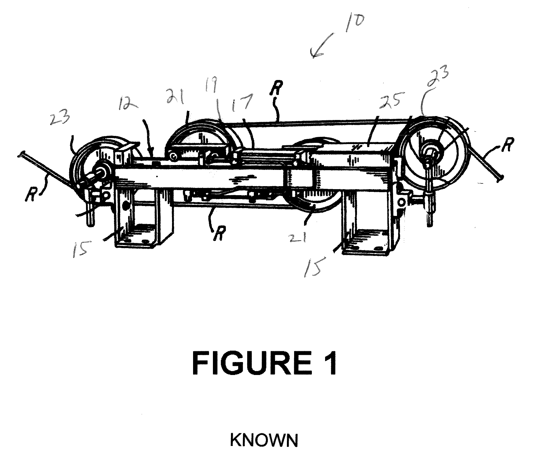
[0017]An existing tensioning apparatus 10 is shown in FIG. 1 to include an H-shaped beam 12 and support brackets 15 for the beam. Air cylinders 17 are mounted on each side of the beam and each includes a piston rod 19. A pair of sheaves 21 move longitudinally along the beam. Rope R extends under guide sheaves 23 and more than 180° degrees around sheaves 21. A cover 25 may extend the full length of beam 12.

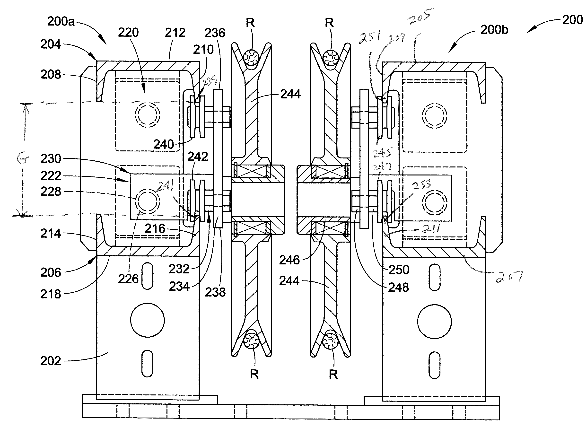
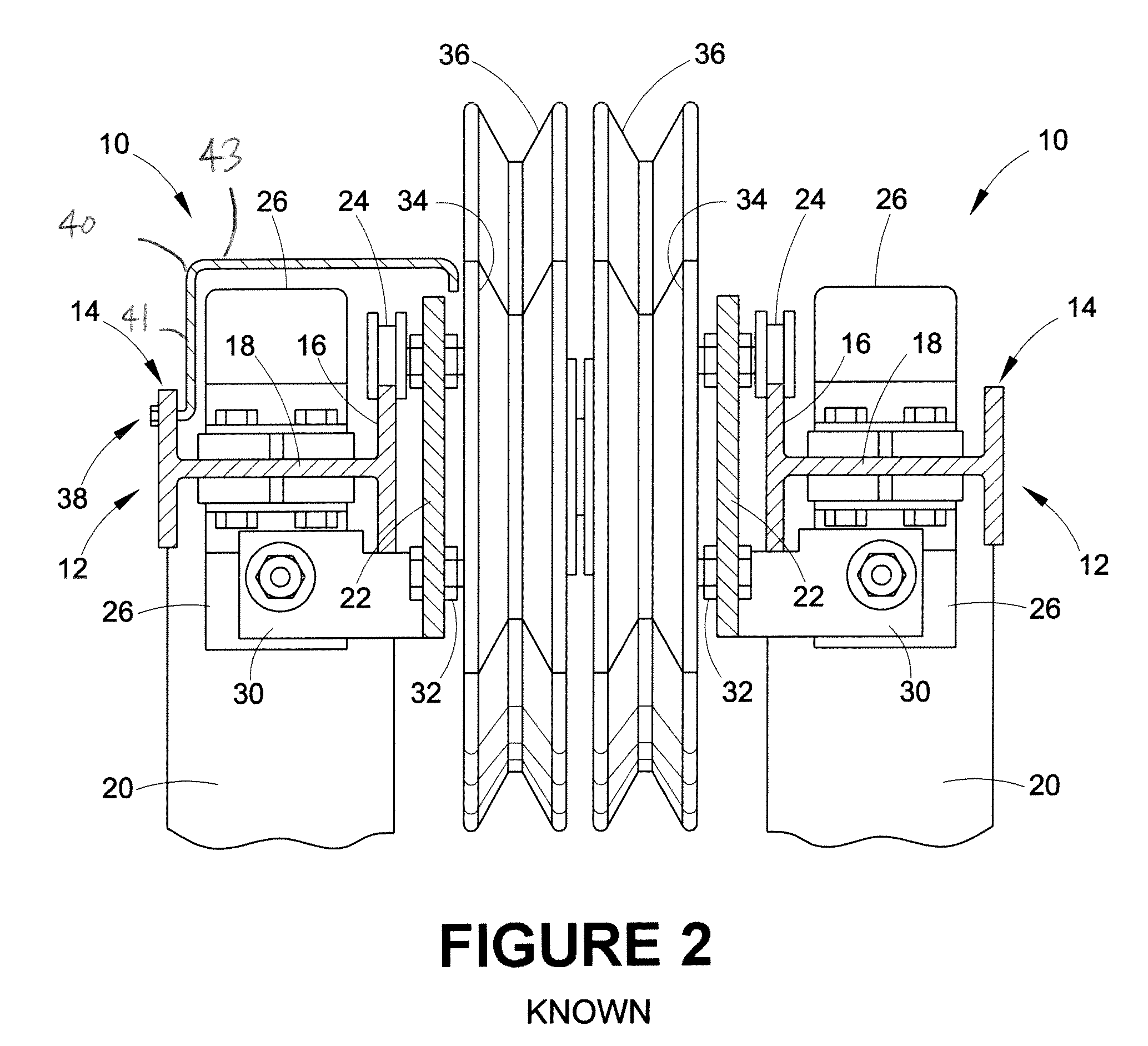
[0018]A known dual tensioning apparatus 10 is shown in FIG. 2 to include an elongate H-shape beam frame 12 having a pair of spaced apart, parallel flanges 14, 16 and an interconnecting web portion 18 extending between the pair of flanges. The flanges 14, 16 are supported by mounting brackets 20 approximately situated at terminal ends of the apparatus 10. The innermost flange 16 of the H-beam 12 supports a carriage, which includes a carriage plate 22 having a lateral length that is greater than the adjacent flange. A lateral length (i.e., height) of the carriage plate 22 extends alo...


PUM


Abstract

A tensioning apparatus includes a first C-shaped beam frame spaced apart from a second C-shaped beam frame. A first air cylinder is suspended from the first beam frame and a second air cylinder is mounted on the second beam frame. A carriage assembly is situated adjacent to the first and the second air cylinders. At least two pairs of guide members are supported on opposing corners of a support member of the carriage assembly. The pairs of guide members guide the carriage assembly along a longitudinal extent of the first and the second beam frames. The guide members travel along distal edges of flanges of the beam frames. A power operated means actuates movement of the carriage assembly along the first and second beam frames. A rope guide sheave is supported by the carriage assembly for free rotation.

Description

CLAIM OF PRIORITY[0001]The present application claims priority from U.S. provisional application Ser. No. 61 / 077,672, filed Jul. 2, 2008, which is incorporated by reference herein.BACKGROUND OF THE DISCLOSURE[0002]The present disclosure is directed generally toward a rope tensioning apparatus and, more particularly, to an apparatus that includes at least two spaced apart beam frames that are situated exterior to air cylinders secured thereon.[0003]Known apparatuses for producing a web of paper direct at least one continuous rope several times around multiple rolls for threading and pinching a tail of a web through the rolls. The continuous rope requires substantial take-up to maintain a desired tension; however, the rolls are driven at speeds in excess of 17 feet / second, which can cause the continuous rope to stretch up to ten percent in length over a period of use.[0004]Therefore, rope stretchers preferably maintain constant tension in the continuous rope. Some known rope stretcher...

Claims


Application Information

Patent Timeline
Patent Type & Authority Applications(United States)
IPC IPC(8): F16H7/12
CPCD21G9/0072
Inventor PAYNE, JAMESCRINKEY, KEITH
Owner CUSTOM THREADING SYST
Why Eureka
Try Eureka