Light guide plate and method for manufacturing the same, and backlight module using the same

a technology of light guide plate and backlight module, which is applied in the direction of instruments, lighting and heating equipment, other domestic objects, etc., can solve the problem of air gap at the boundary

Inactive Publication Date: 2010-01-21
HONG FU JIN PRECISION IND (SHENZHEN) CO LTD +1
View PDF3 Cites 39 Cited by
  • Summary
  • Abstract
  • Description
  • Claims
  • Application Information

AI Technical Summary

Problems solved by technology

However, an air gap exists at the boundary between

Method used


Image

  • Light guide plate and method for manufacturing the same, and backlight module using the same
  • Light guide plate and method for manufacturing the same, and backlight module using the same
  • Light guide plate and method for manufacturing the same, and backlight module using the same

Examples


Embodiment Construction

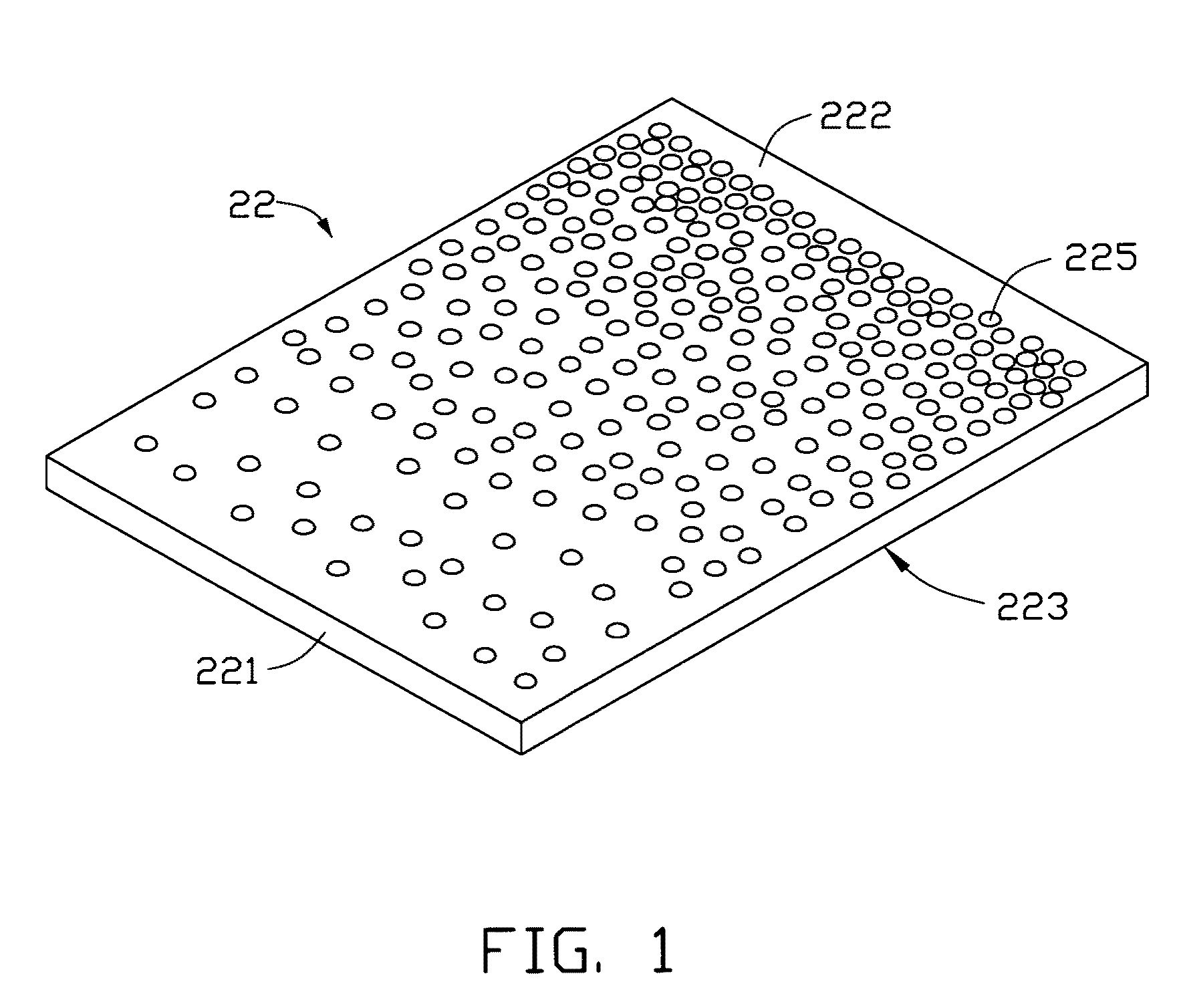
[0015]Referring to FIG. 1, an embodiment of a light guide plate 22 is a transparent plate, and includes a light input surface 221 located at a side surface of the light guide plate 22, a light output surface 222 adjoining the light input surface 221, and a reflecting surface 223 opposite the light output surface 222. The light guide plate 22 includes a plurality of scattering microstructures 225 irregularly distributed on the light output surface 222. A density of the plurality of scattering microstructures 225 increases with increasing distance from the light input surface 221.

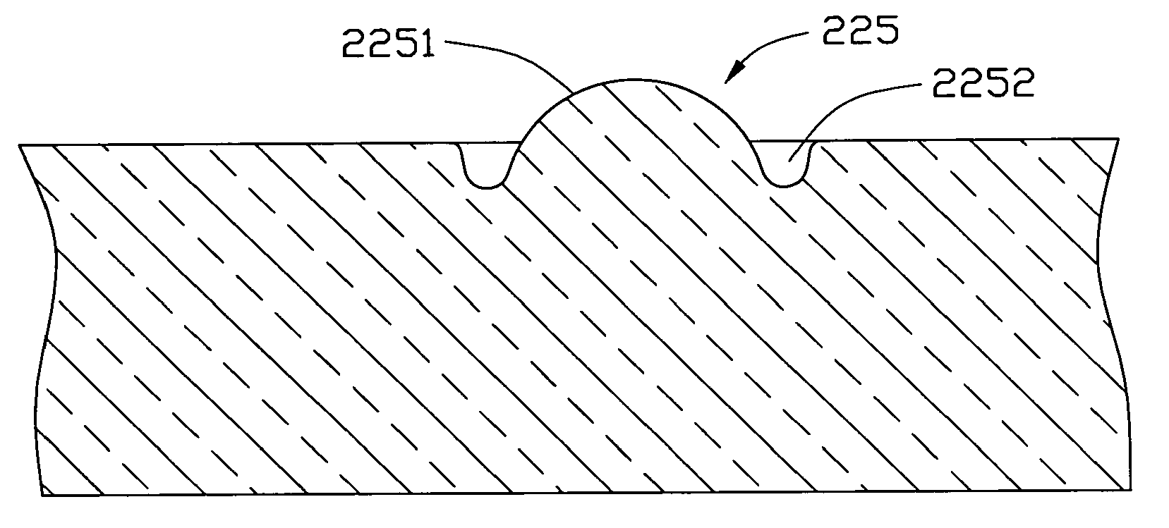
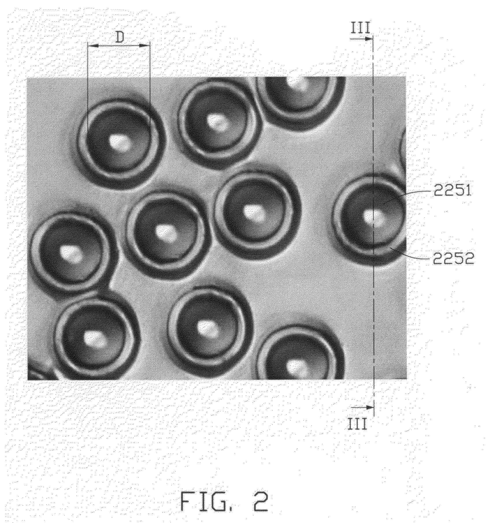
[0016]Referring to FIGS. 2 and 3, each scattering microstructure 225 includes a spherical protrusion 2251 having a substantially spherical surface, and a substantially ring-shaped groove 2252 defined around a periphery of the spherical protrusion 2251. At least half of the spherical surface is as smooth as a mirror. In the illustrated embodiment, at least 90% of the substantially spherical surface is as smoot...


PUM


Abstract

A light guide plate includes a light input surface, a light output surface adjoining the light input surface, and a reflecting surface opposite the light output surface. One of the light output surface and the reflecting surface defines a plurality of scattering microstructures. Each scattering microstructure includes a spherical protrusion having a substantially spherical surface, and a substantially ring-shaped groove defined around a periphery of the spherical protrusion. At least half of the spherical surface is as smooth as a mirror. A method for manufacturing the light guide plate and a backlight module using the light guide plate are also provided.

Description

BACKGROUND[0001]1. Technical Field[0002]The present disclosure relates to a light guide plate for use in a backlight module.[0003]2. Description of Related Art[0004]In a typical liquid crystal display device, a liquid crystal panel of the typical liquid crystal display device relies on a backlight module powered by electricity to supply the light needed to display images and data.[0005]Currently, backlight modules can be classified as either an edge lighting type or a bottom lighting type depending upon the location of lamps within the device. A typical edge lighting type backlight module includes a light source and a light guide plate. The light guide plate includes a light input surface located at a side surface thereof, a light output surface adjoining the light input surface, and a reflecting surface positioned opposite the light output surface. The light source is generally positioned at the light input surface of the light guide plate. The light guide plate may have a pluralit...

Claims


Application Information

Patent Timeline
IPC IPC(8): F21V7/04B29D11/00
CPCG02B6/0036G02B6/0065G02B6/0061
Inventor YUE, GUO-HAN
Owner HONG FU JIN PRECISION IND (SHENZHEN) CO LTD
Why Eureka
Try Eureka