Method and device for removing image fuzzy overlap between frames

An image and blur technology, applied in the direction of instruments, static indicators, etc., can solve the problems of overlapping blur, slow optical response, etc.

Inactive Publication Date: 2005-12-28
VASTVIEW TECH
View PDF1 Cites 5 Cited by
  • Summary
  • Abstract
  • Description
  • Claims
  • Application Information

AI Technical Summary

Problems solved by technology

[0015] However, the optical response of some liquid crystal materials from light to dark is slow, and the optical response value has not yet reached a low enough value during the above-mentioned black line scanning, so it is inevitable that a few of them will still produce a little "afterimage" overlapping blur between pictures The phenomenon

Method used


Image

  • Method and device for removing image fuzzy overlap between frames
  • Method and device for removing image fuzzy overlap between frames
  • Method and device for removing image fuzzy overlap between frames

Examples


Embodiment 1

[0077] The following reference figure 1 , Figures 3a, b and Figures 4a to d illustrate a first embodiment of the present invention.

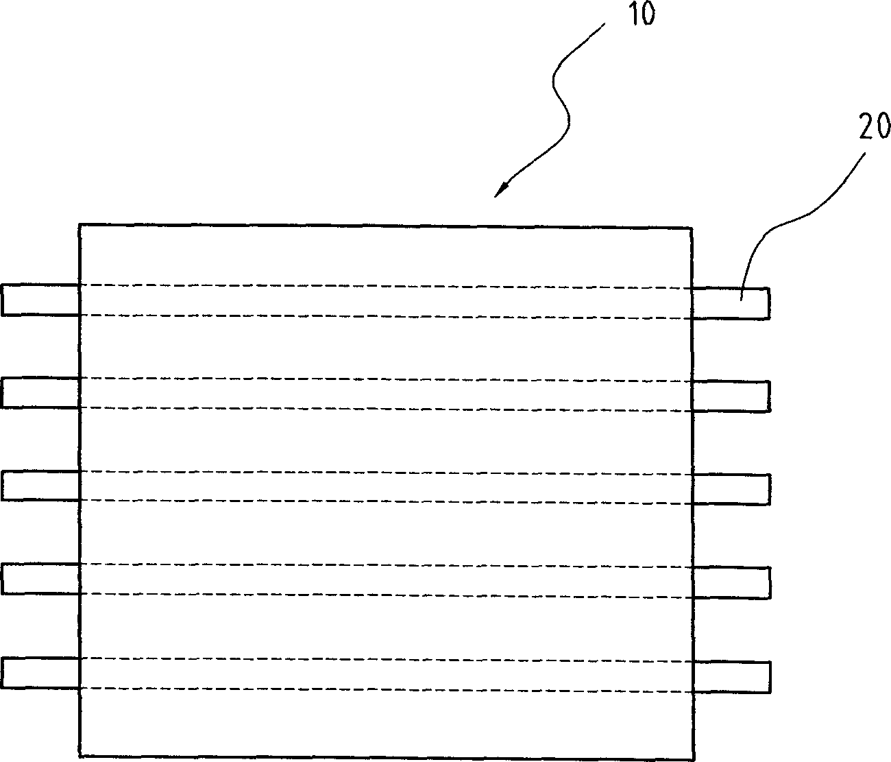
[0078] First, please refer to figure 1 , which shows the arrangement structure of the liquid crystal display panel and the backlight unit used in the first embodiment of the present invention.

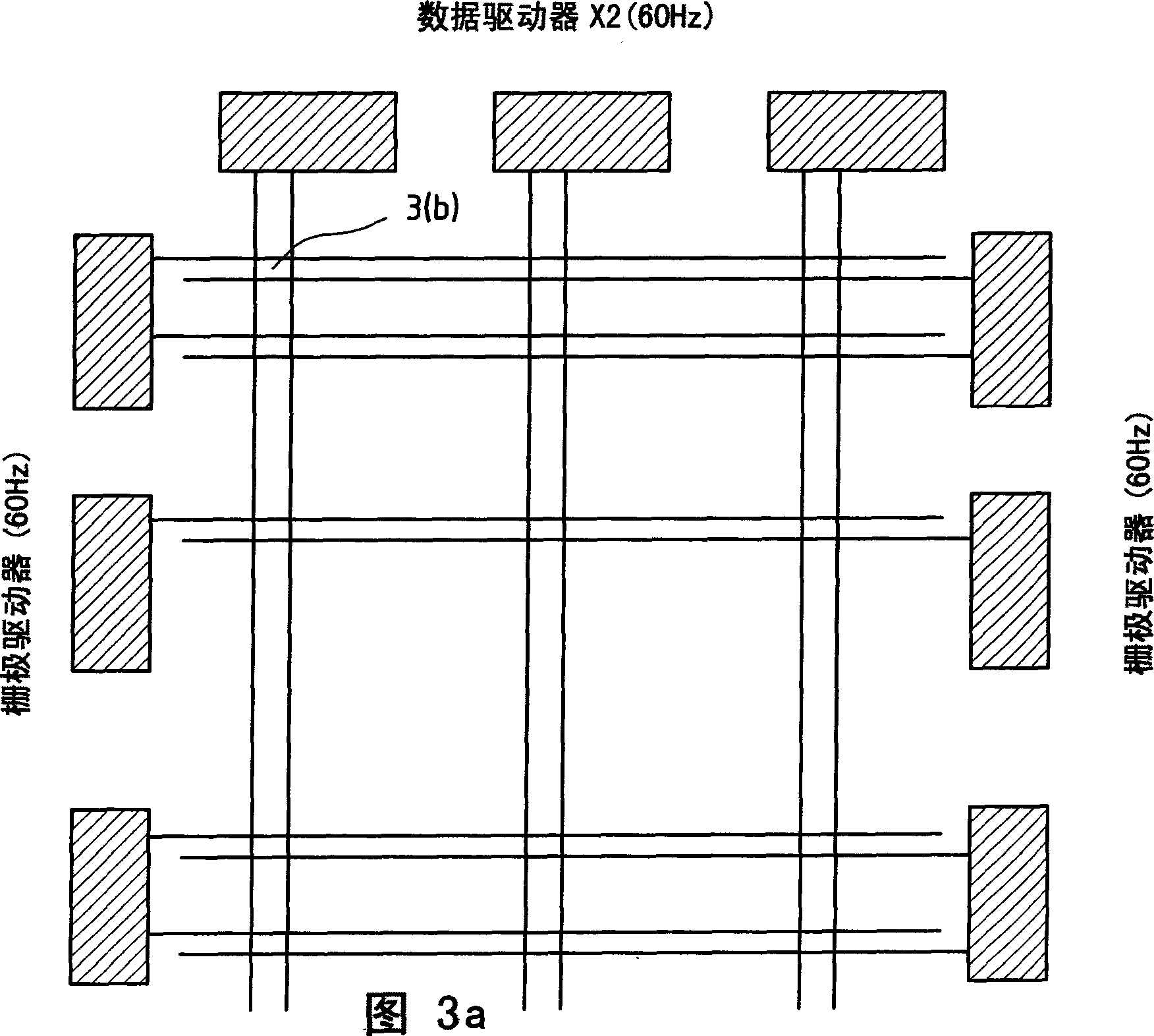
[0079] FIG. 3 a shows a pixel array formed by intersections of a plurality of gate lines and data lines and an analog driving circuit formed by a plurality of data drivers and a plurality of gate drivers according to this embodiment.

[0080] Figure 3b is an analog driving device for a liquid crystal display according to this embodiment. Figure 3b It is an enlarged view of the place marked 3b in Fig. 3a.

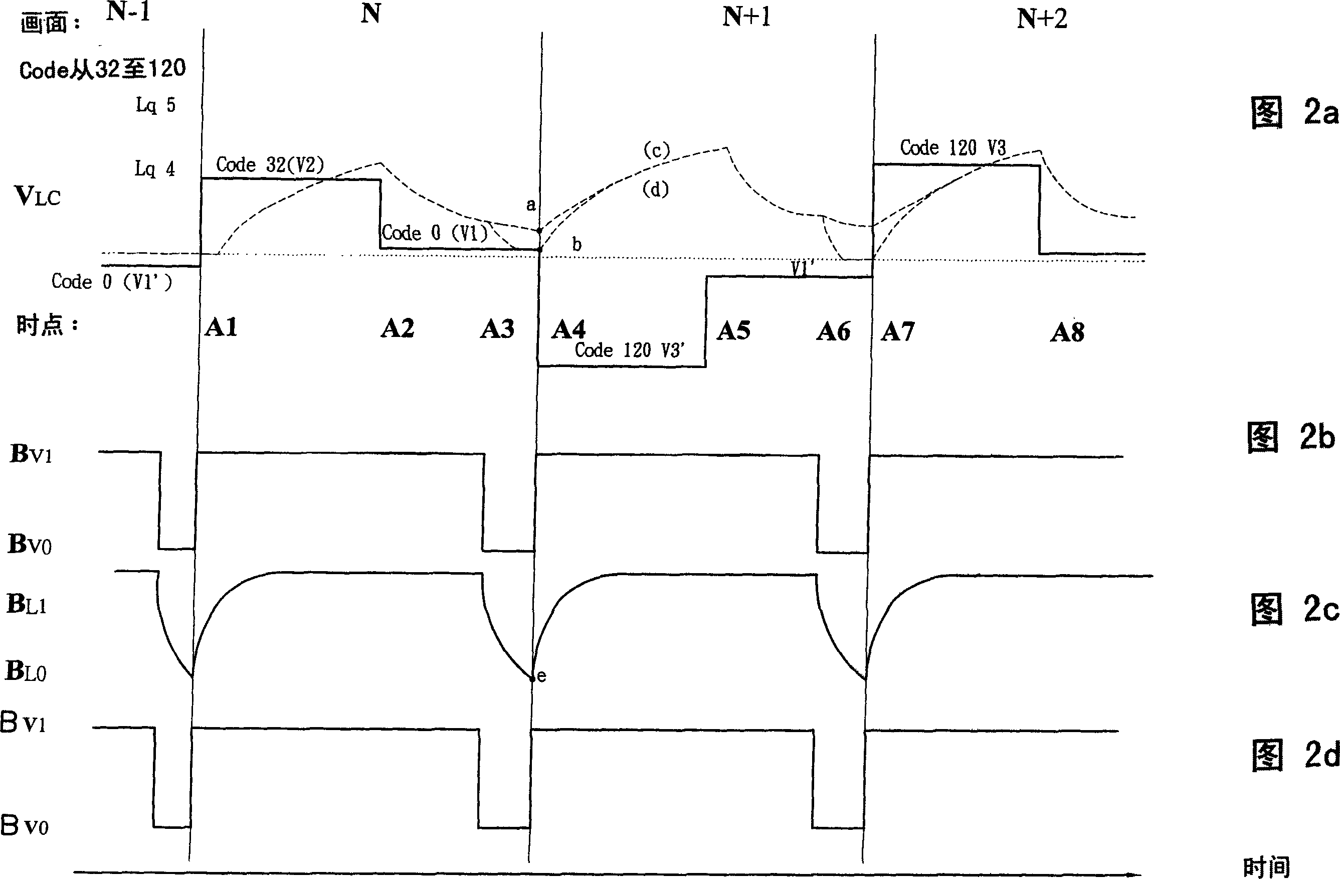
[0081] Fig. 4a to 4d are the liquid crystal driving voltage pulse V produced by the analog driving device of Fig. 3a, b of the present embodiment LC , the liquid crystal sum optical response Lq, the backlight control voltage BV and the backlight...

Embodiment 2

[0115] The following reference figure 1 , Figures 5a, b and Figures 6a to d illustrate a second embodiment of the present invention.

[0116] First, please refer to figure 1 , which shows the arrangement structure of the liquid crystal display panel and the backlight unit used in the second embodiment of the present invention.

[0117] FIG. 5 a is a pixel array formed by intersections of multiple gate lines and data lines and an analog driving circuit formed by multiple data drivers and multiple gate drivers according to the present embodiment.

[0118] Figure 5b is a liquid crystal display analog drive device according to this embodiment. Figure 5b It is an enlarged view of the place marked 5b in Fig. 5a.

[0119] Fig. 6b is an analog driving device for a liquid crystal display according to this embodiment.

[0120] 6a to 6d are the liquid crystal driving voltage pulses V generated by the analog driving device of Fig. 5a and b of this embodiment. LC , the liquid cryst...

Embodiment 3

[0146] The following reference figure 1, Figures 7a, b and Figures 8a to d illustrate a third embodiment of the present invention.

[0147] First, please refer to figure 1 , which shows the arrangement structure of the liquid crystal display panel and the backlight unit used in the third embodiment of the present invention.

[0148] FIG. 7 a is a pixel array formed by intersections of a plurality of gate lines and data lines, and an analog driving circuit formed by a plurality of data drivers and a plurality of gate drivers according to the present embodiment.

[0149] Figure 7b is a liquid crystal display analog drive device according to this embodiment. Figure 7b It is an enlarged view of the place marked 7b in Fig. 7a.

[0150] Fig. 8 a to 8 d are the liquid crystal drive voltage pulse V that the analog driving device of Fig. 7 a, b of the present embodiment produces LC , the backlight control voltage BV, the backlight brightness response BL, and the liquid crystal s...


PUM


Abstract

A device for removing off overlap and fuzzy of image between pictures consists of the first and the second input control line, the first and the second input data line, the first and the second capacitor, output driving voltage line, the first and the second transistor, back light unit and back light voltage input control line. It features that the first and the second capacitors are earthed, the first and the second input control lines are connected to grid driver and the first and second input data lines are connected to data driver.

Description

technical field [0001] The present invention relates to a method and a device for removing image overlap and blur between pictures in the process of simulating CRT pulse-type development, in particular to a method and a device for removing the overlap and blur of residual images between pictures in the process of simulating CRT pulse-type development with a liquid crystal display . Background technique [0002] Due to the widespread use of liquid crystal display (LCD) devices, there are various types of products ranging from consumer electronics products to computer and mobile phone wireless communication applications, making the technology of LCDs develop rapidly. It is in line with the development trend of future electronic products towards the characteristics of light and small, low power consumption, low heat dissipation, etc., especially the liquid crystal display technology is enough to overcome the limitations of traditional or other current display technologies such ...

Claims


Application Information

Patent Timeline
Patent Type & Authority Applications(China)
IPC IPC(8): G09G3/36
Inventor 沈毓仁陈政嵘
Owner VASTVIEW TECH
Why Eureka
Try Eureka