

Self-contained refuge chamber
a self-contained, chamber technology, applied in separation processes, auxillary pretreatment, filtration separation, etc., can solve the problem of no provision for controlling the climate within the closed environment, and achieve the effect of prolonging the life-sustaining environment within the accommodation zon
- Summary
- Abstract
- Description
- Claims
- Application Information
AI Technical Summary
Benefits of technology
Problems solved by technology
Method used
Image

Examples
first embodiment
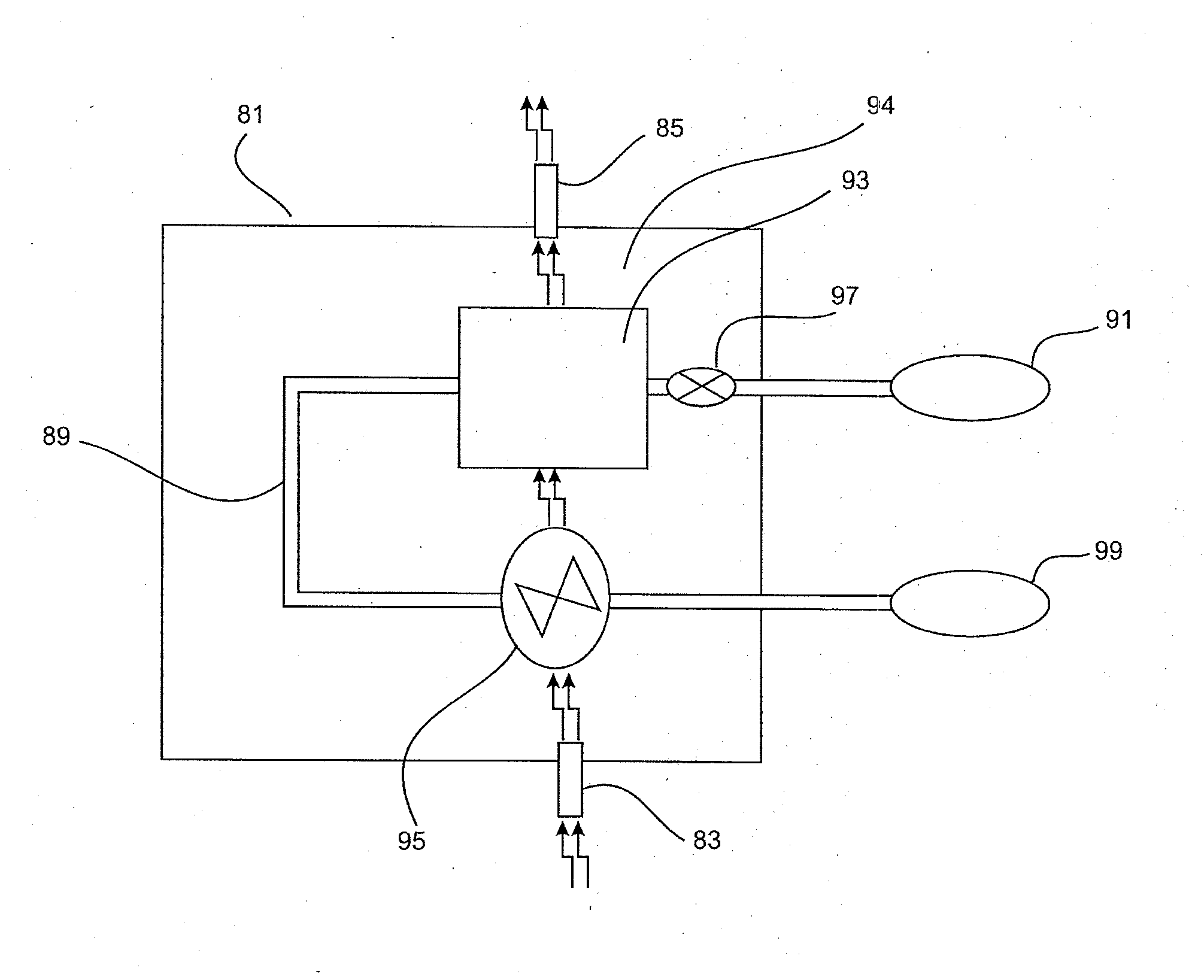
[0050]FIG. 5 shows the apparatus 81 according to the invention. The apparatus 81 comprise a working fluid path 89 incorporating a treating means 93 and pump means 95. The pump means 95 allow interaction between the air undergoing treatment and the treating means 93.
[0051]The treatment means 93 comprises a heat exchanger as will be explained later. The working fluid operates the heat exchanger in the sense that it passes in heat exchange relation therewith, thereby being an integral part of the operation of the heat exchanger.
[0052]The pump means 95 is operable in response to the flow of the working fluid through the working fluid flow path. Typically, the pump means 95 includes a turbine with which the flow of working fluid interacts to drive the pump means 95.
[0053]The pump means 95 comprise a fan systems and / or bellow systems for delivery of the air to the treatment means 93. The treatment means 93 and the pump means 95 are operated by a working fluid flowing through the fluid pat...
second embodiment
[0063]As shown in FIG. 6, the apparatus 81 according to the invention comprises, in addition to the previously described treatment means 93 for reducing the temperature of the air, further treatment means 101 and 103. Treatment means 101 and 103 are connected along the working fluid path 89 and located downstream with respect to treatment means 93 and upstream with respect to pump means 95. In this arrangement, the working fluid after passing through the treatment means 93 is conducted via the working fluid path 89 to operate treatment means 101 and 103 for further treatment of the air 87. Valve means 97 (previously described) are incorporated along the working fluid path upstream of the treatment means 93 to control the flow of the working fluid from cylinders 91 into the working fluid path 89. In this embodiment the working fluid may be released at a rate of 0-30 Kg / hour.
[0064]The treatment means 101 and 103 incorporate, respectively, air inlets 105 and 107 and air outlets 109 and...
third embodiment
[0095]FIG. 12 shows a second arrangement of the apparatus 81 of the invention. In this arrangement, the working fluid is delivered from the cylinder 91 through the tube heat exchanger 157 and the capillary tubes 159 to the first radiator 155a. A valve system 169 provides control of the working fluid flow into the first radiator 155a. The valve system 169 comprises a plurality of adjustable on / off valves. After operating the first radiator 155a, the working fluid is delivered to the second radiator 155b for operation thereof. The working fluid is then delivered to the tube heat exchanger 157 for cooling of the working fluid that exits the cylinder 91 and which will be fed into the first radiator 155a. The output of the tube heat exchanger 157 is operatively connected to the inlet of the third radiator 155c for delivery of the working fluid exiting the tube heat exchanger 157. After operating the third radiator 155c the working fluid is forwarded to the pump means 95 for operation the...
PUM
| Property | Measurement | Unit |
|---|---|---|
| boiling temperature | aaaaa | aaaaa |
| pressure | aaaaa | aaaaa |
| temperature | aaaaa | aaaaa |
Abstract
Description
Claims
Application Information