Seating system and a passenger accommodation unit for a vehicle

a seating system and passenger technology, applied in the direction of aircraft floors, applications, air-treatment apparatus arrangements, etc., can solve the problems of increasing the pitch between adjacent rows of seats, not being able to meet the needs of passengers on longer flights, and many passengers' sleep problems

Inactive Publication Date: 2007-03-29
VIRGIN ATLANTIC AIRWAYS
View PDF99 Cites 31 Cited by
  • Summary
  • Abstract
  • Description
  • Claims
  • Application Information

AI Technical Summary

Benefits of technology

[0012] An embodiment of the present invention provides improved passenger accommodation for a business-class section of a passenger aircraft. In particular, an embodiment of the invention provides such accommodation which incorporates a flat sleeping surface of maximal length and preferably also of maximal width.

Problems solved by technology

Whilst the above-described arrangement of conventional aircraft passenger-seats is generally satisfactory for short-haul flights having a duration of up to three or four hours, it is not satisfactory for use on longer flights during which passengers typically wish to go to sleep.
Many passengers find it difficult to sleep properly, if at all, when sitting.
A disadvantage of such a system is that the pitch between adjacent rows of seats must be increased substantially to accommodate the full height of a passenger.
Whilst this is sometimes possible in the first-class area of an aircraft cabin, it is generally uneconomic for a business-class cabin.
Furthermore, whilst it is possible to form a generally flat surface which is disposed substantially horizontally, the surface is still not ideal, because the foam or other padding on the seat is generally sculptured for use as a seat, whereas for a bed, it is desirable to have a substantially flat surface.
However, the seating unit of GB 2326824 A represents an even greater overhead in turns of cabin space than the conventional system described above and, moreover, still suffers from the disadvantage that the seat cushioning is designed principally for use as a seat and not a bed.
A disadvantage of the seat of GB 2326824 A is that it occupies a very large floor area within the cabin and, in view of its overall length, the seating unit of GB 2326824 A is wholly unsuitable for use in a business class section of an aircraft.
However, the seating unit of WO 00 / 21831 A2 is still extravagant in terms of the space available within a typical business-class cabin and also suffers from the disadvantage that when configured as a bed, each seat is unable to accommodate comfortably tall passengers.
As with the other prior art seats described above, each of the seats of the seating unit of WO 00 / 21831 A2 also suffers from the disadvantage that the seat cushioning is not specifically designed for use as a bed surface, but is contoured for use principally as a seating surface.
A further disadvantage associated with the seating unit of WO 00 / 21831 A2 is that in order to accommodate a maximal head count within a business class cabin, the seat width is reduced, which many passengers find to be uncomfortable.
Furthermore, privacy screens are provided between adjacent seating units which, in combination with the total number of seating units provided in the limited space afforded by a business class cabin, result in the cabin as a whole having a somewhat crowded appearance.
However, the installation of FR 987559 A is not suitable for use on a passenger aircraft where the aisles must be kept unobstructed at all times and, furthermore, a plurality of adjacent seats are used to provide support for a single couchette.
Thus the installation of FR 987559 A is not able to provide one couchette per seat.

Method used


Image

  • Seating system and a passenger accommodation unit for a vehicle
  • Seating system and a passenger accommodation unit for a vehicle
  • Seating system and a passenger accommodation unit for a vehicle

Examples


Embodiment Construction

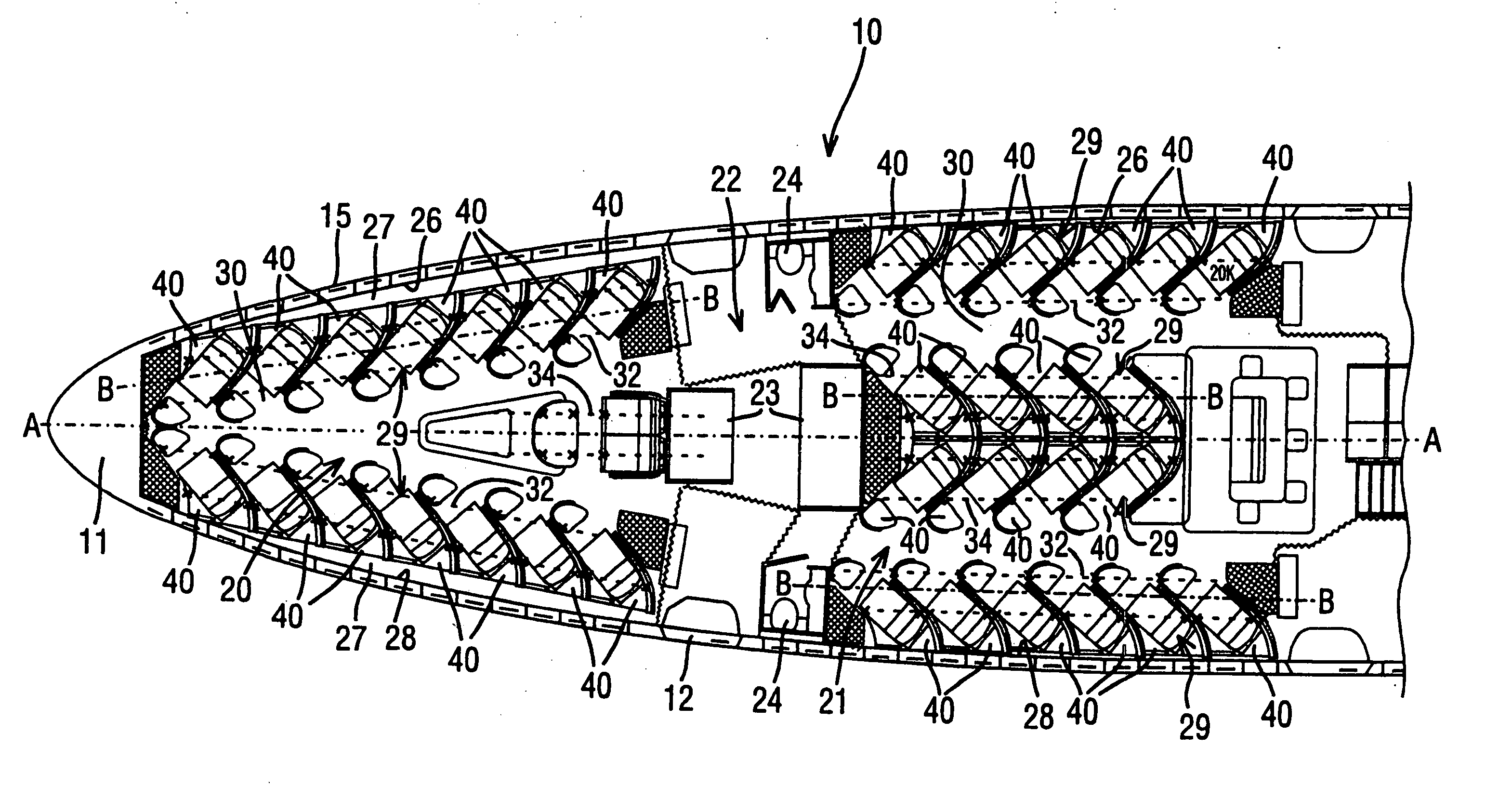
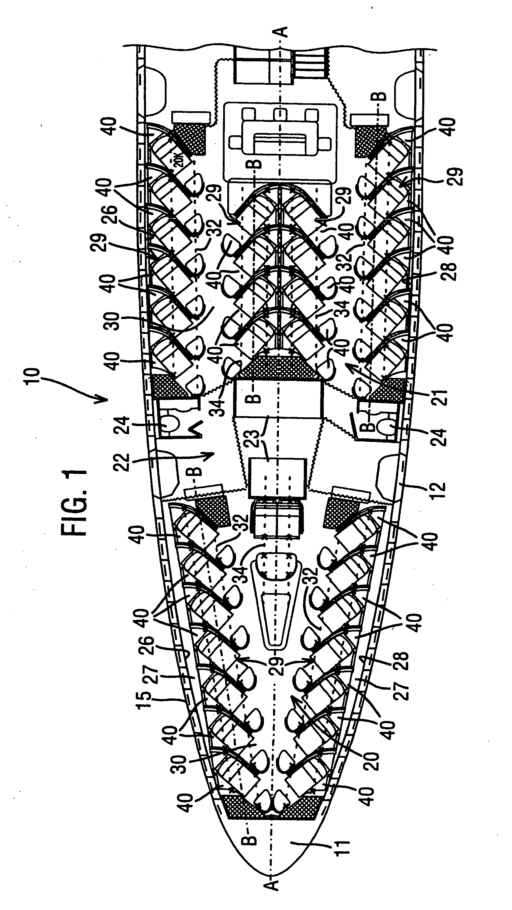
[0127] A passenger aircraft generally comprises a hollow, spindle-shaped fuselage having a front end and a rear end. A front end portion 12 of a typical aircraft fuselage 10, which is disposed towards the front end 11, is shown in FIG. 1 of the accompanying drawings, by way of example. Said fuselage 10 defines a longitudinal aircraft axis indicated by the chain-dot-line A-A in FIG. 1 between the front and rear ends, and the fuselage 10 tapers towards the front end 11 to form a nose portion 15.

[0128] The fuselage 10 accommodates many of the functions and facilities of the aircraft, including one or more passenger accommodation cabins 20, 21. The number and size of the passenger cabins 20, 21 provided on a given aircraft depends on the space available within the fuselage for passenger accommodation and on the desired configuration of the passenger accommodation. The present invention is not limited to the use of any particular shape, size or number of passenger cabins. However, in FI...


PUM


Abstract

A passenger seat assembly for a vehicle, particularly an aircraft, which is adapted to provide self-contained, individual seating and sleeping accommodation for a passenger, said seating assembly includes a supporting structure (42) for supporting said assembly off the floor of a vehicle; one or more movable, passenger-bearing, structural components (71,72); and means for connecting said movable, structural components to said structure such that said components can be selectively moved between a seat configuration, in which a plurality of passenger-bearing surfaces on said one or more structural, movable components (71,71) or said supporting structure form a seat for the passenger, and a bed configuration, in which a plurality of said bearing surfaces (47,48,67,74,76) are disposed substantially coplanarly and substantially contiguously to form a bed for the passenger; characterized in that at least one of said movable components (72) is double-sided, comprising first and second opposite sides, one of said sides having a first seat surface (73) that forms part of the seat in said seat configuration, and the other side having a second bed surface (74) that forms part of said bed in said bed configuration.

Description

CROSS REFERENCE TO RELATED APPLICATIONS [0001] This application is a divisional application of U.S. patent application Ser. No. 10 / 774,244, filed Feb. 6, 2004, hereby incorporated by reference.FIELD OF THE INVENTION [0002] The present invention relates to a novel seating system for a passenger vehicle, particularly an aircraft. The present invention also relates to a passenger accommodation unit for a vehicle, which accommodation unit is adapted to provide individual, self-contained seating and sleeping accommodation for a passenger. The accommodation unit of the present invention may be adapted for use on any passenger vehicle, including omnibuses, coaches, ferries and railway carriages, but is particularly suited for use on aircraft. The present invention also comprehends improvements in or relating to passenger seats for vehicles, particularly aircraft. BACKGROUND OF THE INVENTION [0003] A conventional passenger seat for an aircraft comprises a back-rest and a seat-pan that are s...

Claims


Application Information

Patent Timeline
Patent Type & Authority Applications(United States)
IPC IPC(8): B64D11/06A47C1/035B60N2/20B60N2/30B60N2/34B64D11/00
CPCB60N2/206B60N2/3031B60N2/3065B60N2/309B60N2/34B64D11/00B64D11/0604B60N2/20B64D11/064B64D11/0601B64D11/0641B64D11/0626B64D11/06B64D11/0606B64D11/0646B64D11/0696
Inventor FERRY, DAVIDWELLS, ADAM BERNARDMILES, LUKELAWLER, ANDREW LESLIESTARKEY, DAVID EDWARDMILLS, SIMON FREDERICKDOY, GARY
Owner VIRGIN ATLANTIC AIRWAYS
Why Eureka
Try Eureka