Surgical implants for percutaneous lengthening of spinal pedicles to correct spinal stenosis

a technology of spinal pedicles and surgical implants, which is applied in the field of corrective spinal procedures, can solve the problems of excessive blood loss, reduce the desirability of spinal laminectomy, and disable back and leg pain, and achieve the enhancement of anteriorly directed force vectors and improved accommodation of variations

Active Publication Date: 2016-09-20
INNOVATIVE SURGICAL DESIGNS
View PDF17 Cites 24 Cited by
  • Summary
  • Abstract
  • Description
  • Claims
  • Application Information

AI Technical Summary

Benefits of technology

[0006]The present invention provides several novel devices allowing improved accommodation of the variations in pedicle anatomy and allowing for the offset between the upper and lower bone segments of a vertebra occurring at the site of a pedicle osteotomy. The devices of the present invention are particularly pertinent when a subject pedicle has high convergence angle. The various embodiments disclosed herein involve a series of implantable devices having an upper and a lower portion bridged by a longitudinal (inner) member. All embodiments provide for neutralization of medially directed force vectors, and enhancement of anteriorly directed force vector, during a pedicle lengthening process.

Problems solved by technology

Spinal stenosis, or narrowing of the spinal canal, affects millions of people, leading to disabling back and leg pain due to compression of the spinal nerves.
Although spinal laminectomy can successfully relieve pressure from the spinal nerves, it requires a major surgery and may lead to a variety of complications including spinal instability, excessive blood loss, medical complications, recurrent stenosis and nerve scarring.
These potential problems reduce the desirability of spinal laminectomy and make this operation unsuitable for some elderly patients with significant, pre-existing medical problems.

Method used


Image

  • Surgical implants for percutaneous lengthening of spinal pedicles to correct spinal stenosis
  • Surgical implants for percutaneous lengthening of spinal pedicles to correct spinal stenosis
  • Surgical implants for percutaneous lengthening of spinal pedicles to correct spinal stenosis

Examples


first embodiment

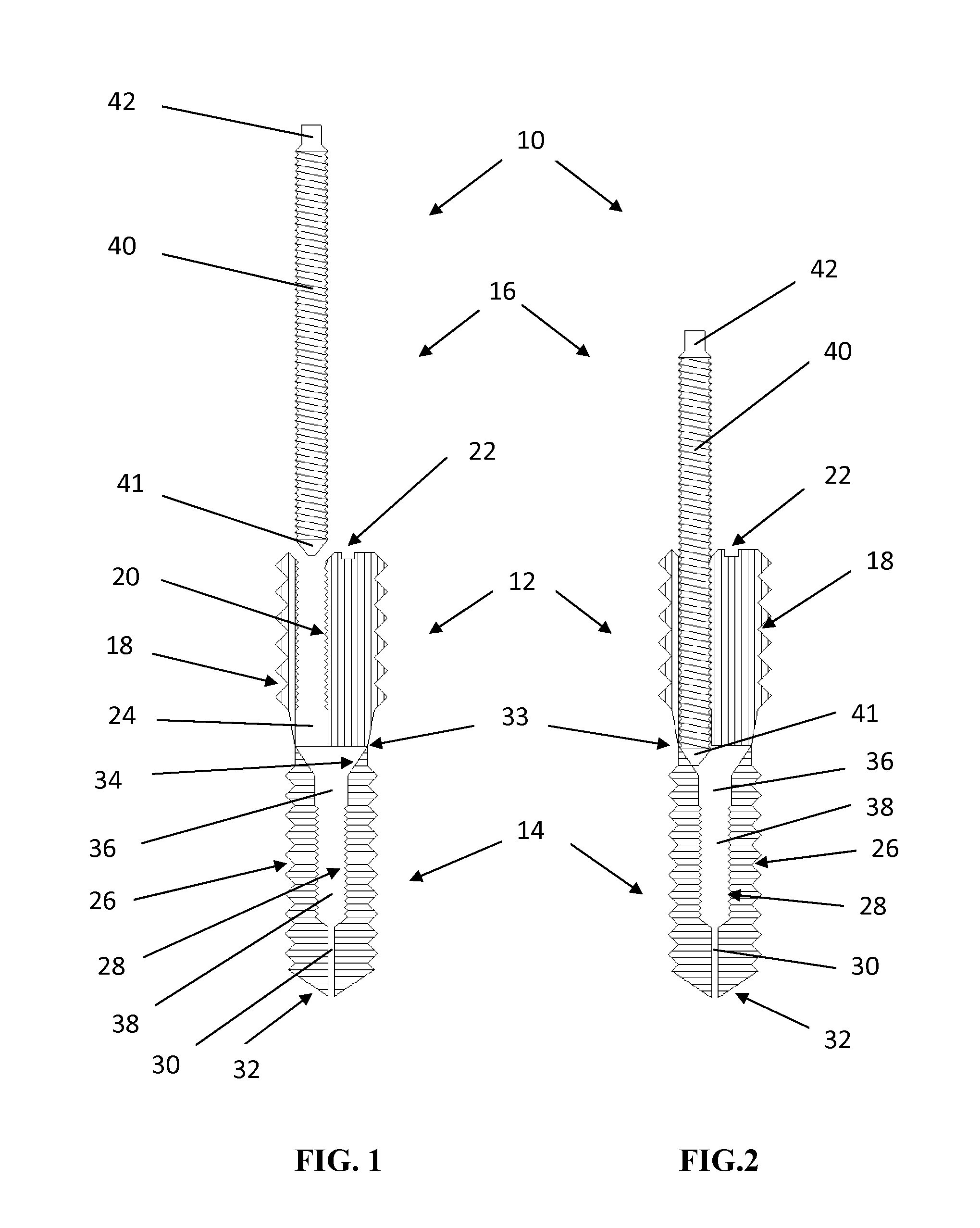
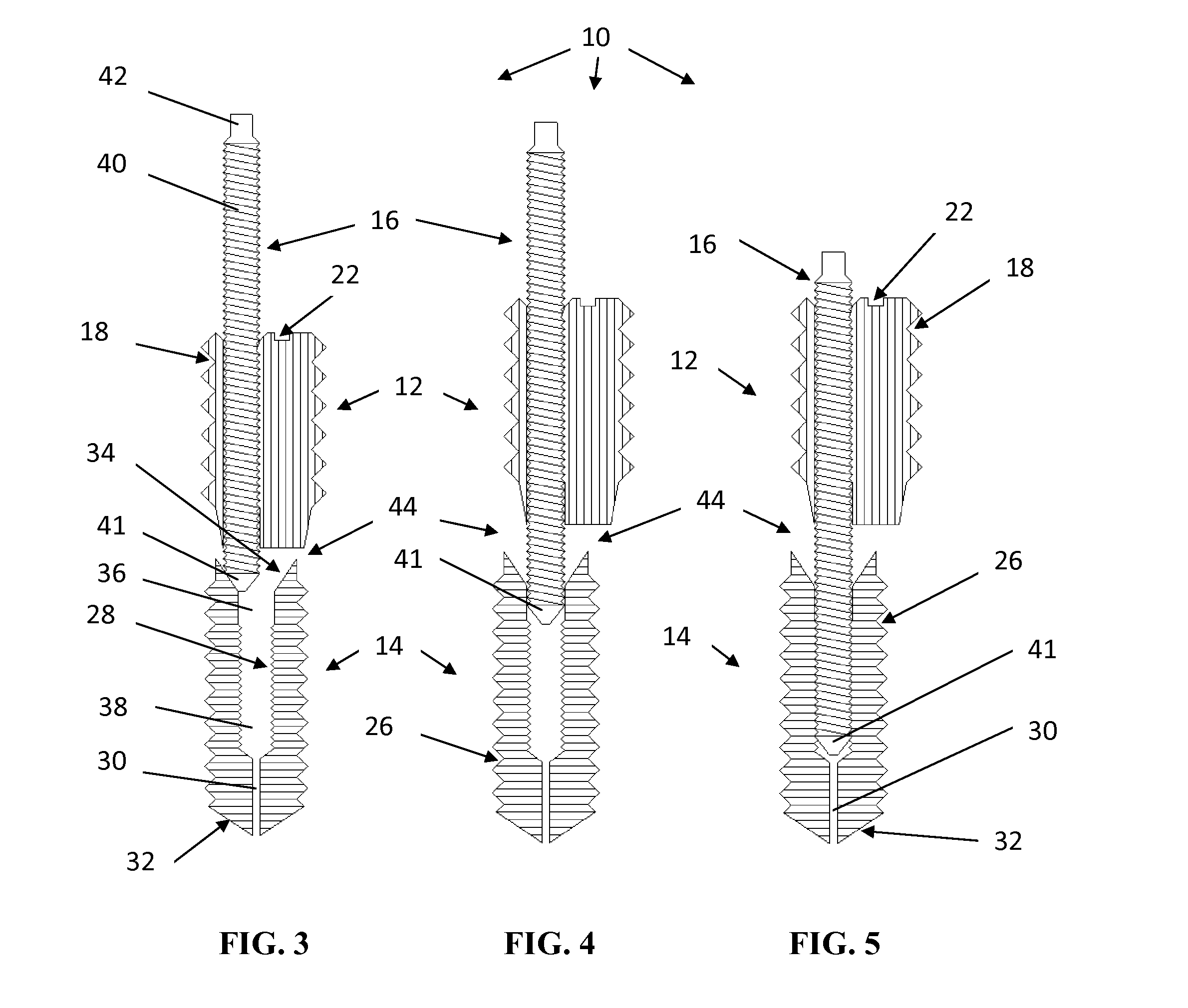
[0068]Referring now to the drawings, where like numeral indicate like elements, there is shown in FIGS. 1-7 a pedicle lengthening device 10 of the present invention. FIG. 1 illustrates an exploded, cross-sectional view of the pedicle lengthening device 10. Primarily including three components in this embodiment, the pedicle lengthening device 10 has an dorsal (upper) implant portion 12, a ventral (lower) implant portion 14, and an inner member (e.g., a threaded rod) 16.

[0069]The dorsal (upper) implant portion 12, in this embodiment, has external threads 18, an internally threaded inner bore (aka offset passage) 20, a driver connection 22, and a distal end 24 of the offset passage. The distal end 24 of the offset passage may be threadless over a portion thereof.

[0070]The ventral (lower) implant portion 14, in this embodiment, has external threads 26, an internally threaded inner bore 28, a cannulated passage 30, and a threaded end 32 (i.e., exterior threads extending to the end). Beg...

second embodiment

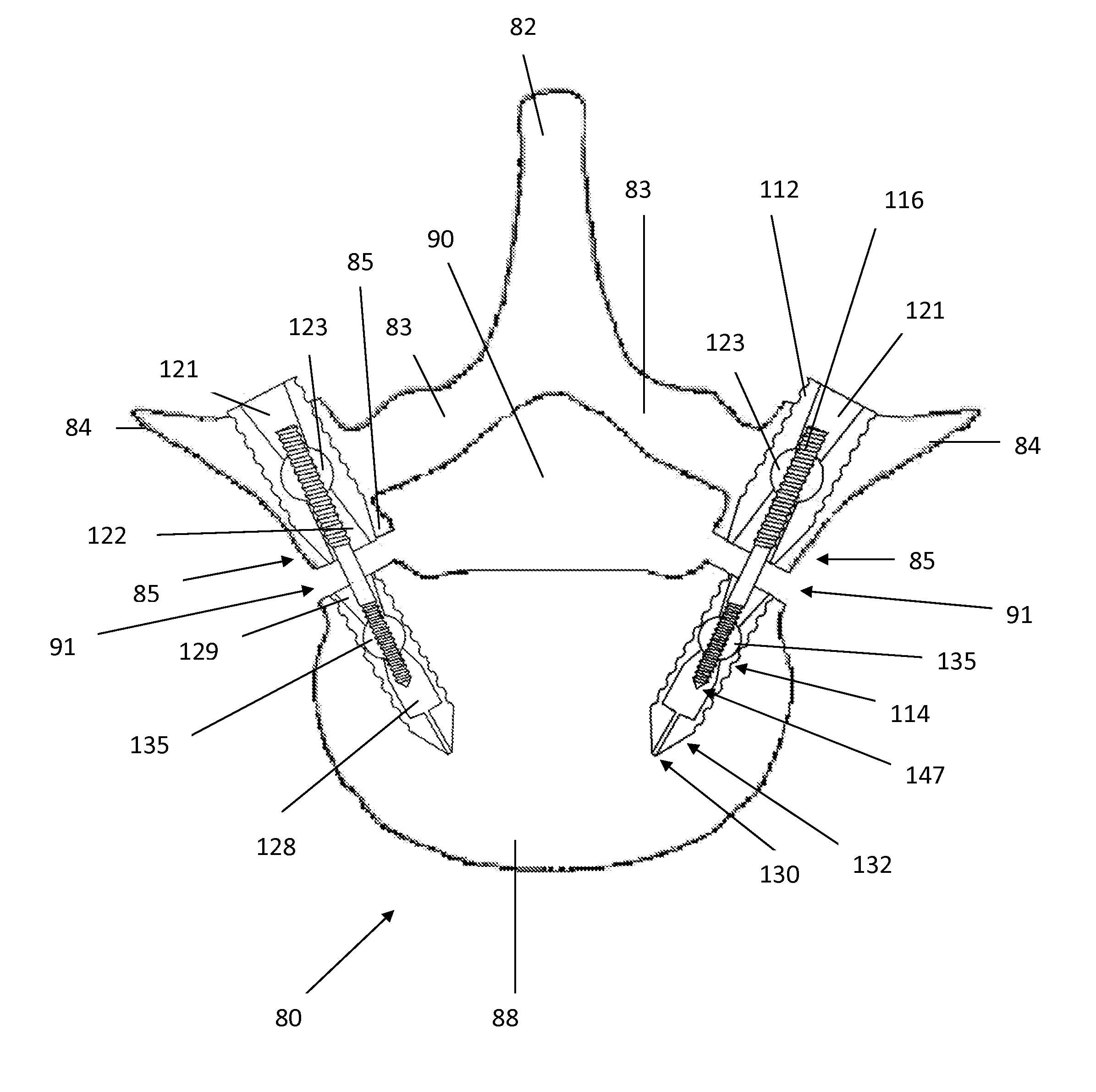
[0077]FIG. 9 illustrates a cross-sectional view of second embodiment of a pedicle lengthening device 110, with the inner member 116 withdrawn from the device 110, showing the dorsal and the ventral portions 112, 114 in their pre-elongated (pre-distracted) position. FIG. 10 is similar, but shows the dorsal and the ventral portions 112, 114 in an elongated (distracted) position.

[0078]The inner member 116, or jack screw, in this embodiment, includes an outer threaded lower surface 141, a proximal driver connection 142, an outer threaded upper surface 143, an unthreaded middle outer surface 145, and a tapered and threaded end 147. The inner member 116 may be dual pitched, where the threads of the outer threaded lower surface 141 are reversed relative to the threads of the outer threaded upper surface 143.

[0079]The dorsal (upper) implant portion 112, in this embodiment, has external threads 118 on a cylindrical portion thereof, and an unthreaded conical exterior surface 119 at a distal e...


PUM


Abstract

An implant to separate a vertebral cut has an upper portion, lower portion, and inner member. The inner member communicates with a swivelable coupling located at each end of the inner member. Each swivelable coupling also interacts with a respective one of the upper and lower portion, within an inner bore thereof. Movement of the inner member relative to one or both of the upper and the lower portions, via one or both swivelable couplings, translates the upper portion away from the lower portion, about a vertebral cut, to widen the vertebral cut and expand the spinal canal. Swivelable action of the couplings allows angulation of the inner member, relative to a longitudinal axis of the implant, to accommodate a natural lateral shift occurring during a widening of a vertebral cut.

Description

RELATED INVENTIONS[0001]This application claims benefit of priority of U.S. Provisional Application No. 61 / 549,848, entitled “Surgical Implants for the Percutaneous Lengthening of the Spinal Pedicles to Correct Spinal Stenosis,” filed Oct. 21, 2011; which application is incorporated herein by reference.FIELD OF THE INVENTION[0002]The present invention relates generally to the field of corrective spinal procedures; and more particularly to a technique and apparatus for expanding a spinal canal by percutaneous cutting of the spinal pedicles and implantation of a novel device capable of lengthening and fixating the pedicles in expanded position.BACKGROUND OF THE INVENTION[0003]Spinal stenosis, or narrowing of the spinal canal, affects millions of people, leading to disabling back and leg pain due to compression of the spinal nerves. Patients with severe spinal stenosis often require major surgery involving a spinal laminectomy, wherein portions of the lamina, spinous process and facet ...

Claims


Application Information

Patent Timeline
Patent Type & Authority Patents(United States)
IPC IPC(8): A61B17/70
CPCA61B17/7071F04C2270/041
Inventor ANDERSON, D. GREGBEAMS, WAYNETURNER, BARRYMORRIS, ED
Owner INNOVATIVE SURGICAL DESIGNS
Why Eureka
Try Eureka