Rotary seal with improved film distribution

Active Publication Date: 2009-01-01
KALSI ENG
View PDF42 Cites 30 Cited by
  • Summary
  • Abstract
  • Description
  • Claims
  • Application Information

AI Technical Summary

Benefits of technology

[0020]It has now been discovered that in the aforementioned cases described in the Background, the lubrication problem occurs because the value of EWH approaches zero or becomes negative—a circumstance not contemplated under the conventional wisdom because EWH and its import were unknown. As seal temperature increases, lubrication decreases as the value of EWH decreases. As lubrication decreases, the seal generates more and more heat due to increasing asperity friction, causing a loss of lubricant film viscosity. These factors further increase seal temperature, compounding the problem and leading to an unsustainable runaway operating condition. Thus, in one embodiment of the rotary seal of the present invention the value of EWH is maintained positive.
[0021]Another embodiment of the present invention is a generally circular, hydrodynamically lubricating rotary seal that accomplishes improved lubrication through the cooperative benefits of a modified zig-

Problems solved by technology

It has now been discovered that in the aforementioned cases described in the Background, the lubrication problem occurs because the value of EWH approaches zero or becomes negative—a circumstance not contemplated under the conventional wisdom because EWH and its import were unkno

Method used


Image

  • Rotary seal with improved film distribution
  • Rotary seal with improved film distribution
  • Rotary seal with improved film distribution

Examples


Example

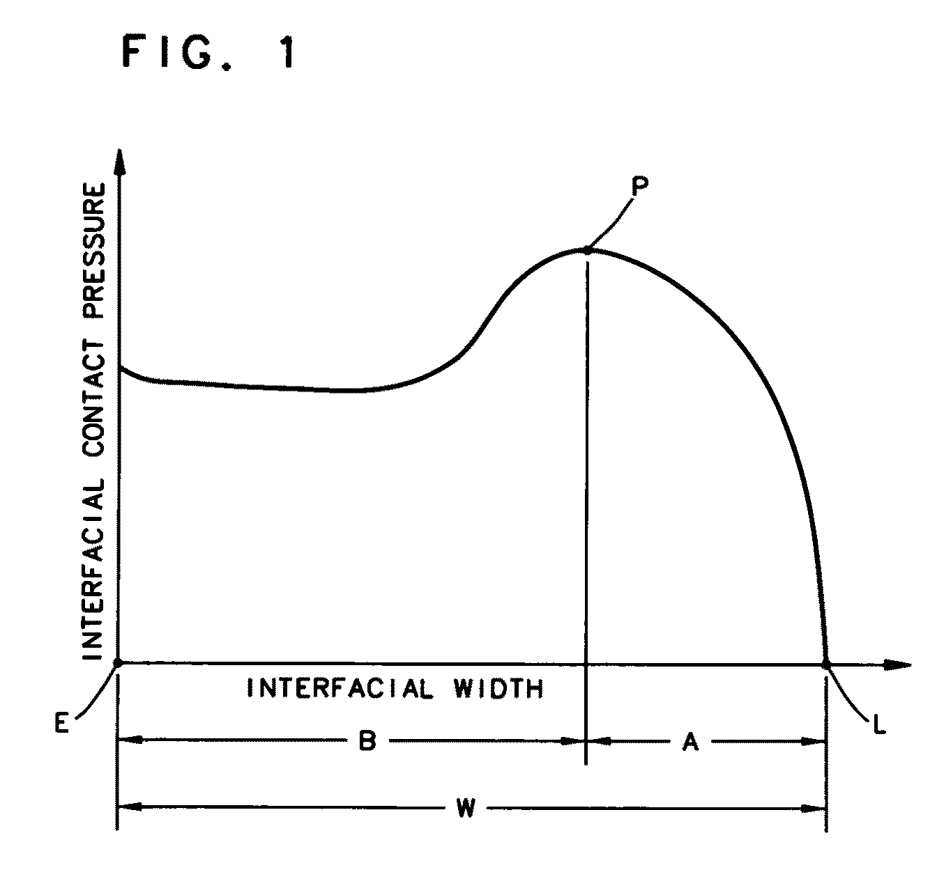
[0052]FIG. 1 is a graph that schematically represents an interfacial contact pressure plot at any circumferential location of a typical seal, for example, manufactured according to one of assignee's U.S. Pat. Nos. 4,610,319, 5,230,520, 6,315,302, 6,382,634, and so forth. The proportions of a contact pressure plot will vary depending on specific seal geometry and analysis constraints, but the general plot characteristics are captured in FIG. 1. The plot has a first footprint edge L and second footprint edge E, which correspond to the lubricant-side and environment-side edges, respectively, of the dynamic sealing interface / footprint. The direction of relative rotation between the seal and the mating relatively rotatable surface is normal (perpendicular) to the axis labeled “interfacial width”, and normal (perpendicular) to the page on which the figure is printed.

[0053]At any given circumferential location of the footprint, the inlet contact pressure rises from zero at the first footpr...


PUM


Abstract

The present invention is a generally circular rotary seal that establishes sealing between relatively rotatable machine components for lubricant retention and environmental exclusion, and incorporates seal geometry that interacts with the lubricant during relative rotation to distribute a lubricant film within the dynamic sealing interface. The features of a variable inlet size, a variable dynamic lip flank slope, and a reduction in the magnitude and circumferentially oriented portion of the lubricant side interfacial contact pressure zone at the narrowest part of the lip, individually or in combination thereof, serve to maximize interfacial lubrication in severe operating conditions, and also serve to minimize lubricant shear area, seal torque, seal volume, and wear, while ensuring retrofitability into the seal grooves of existing equipment.

Description

CROSS-REFERENCE TO RELATED APPLICATIONS[0001]This is a continuation-in-part of U.S. patent application Ser. No. 11 / 386,209 filed Mar. 22, 2006. Applicant claims the benefit of U.S. provisional application Ser. No. 60 / 967,174 filed Aug. 31, 2007, U.S. provisional application Ser. No. 60 / 999,957 filed Oct. 23, 2007, and U.S. provisional application Ser. No. 61 / 067,411 filed Feb. 28, 2008. Applicant incorporates by reference herein U.S. provisional application Ser. Nos. 60 / 967,174, 60 / 999,957 and 61 / 067,411 in their entirety.STATEMENT REGARDING FEDERALLY SPONSORED RESEARCH OR DEVELOPMENT[0002]This invention was made with United States government support under Contract No. DE-FG02-05ER84206 awarded by the Department of Energy. The United States government therefore has certain rights in this invention.BACKGROUND OF THE INVENTION[0003]1. Field of the Invention[0004]This invention relates to hydrodynamic rotary seals for bi-directional rotation that are used to retain a lubricant and excl...

Claims


Application Information

Patent Timeline
IPC IPC(8): F16J15/32
CPCF16J15/164F16J15/3208F16J15/3244F16J15/324F16J15/3236
Inventor DIETLE, LANNIE LAROYSCHROEDER, JOHN ERICK
Owner KALSI ENG
Why Eureka
Try Eureka