Stereo display and display
a display screen and stereo display technology, applied in the field of stereo display, can solve the problems of loss of stereo display effect, user discomfort, and the inability of stereo display to use liquid crystal display (lcd) as its display screen
- Summary
- Abstract
- Description
- Claims
- Application Information
AI Technical Summary
Benefits of technology
Problems solved by technology
Method used
Image
Examples
first embodiment
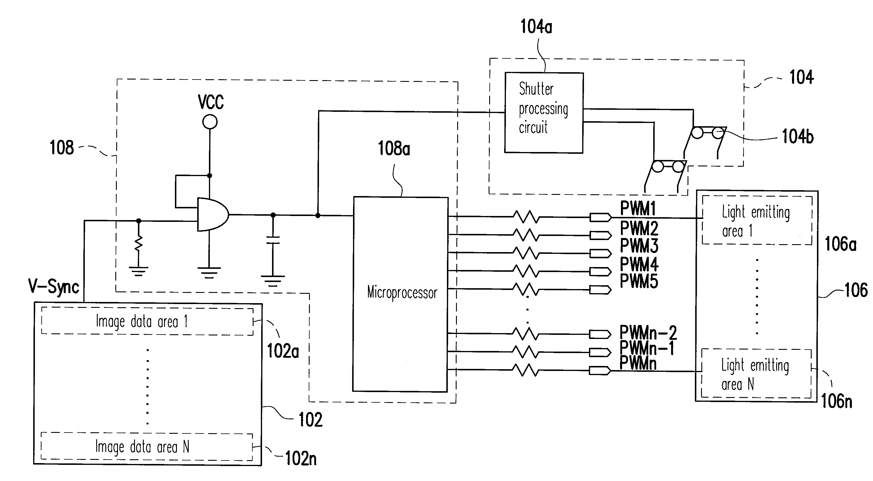
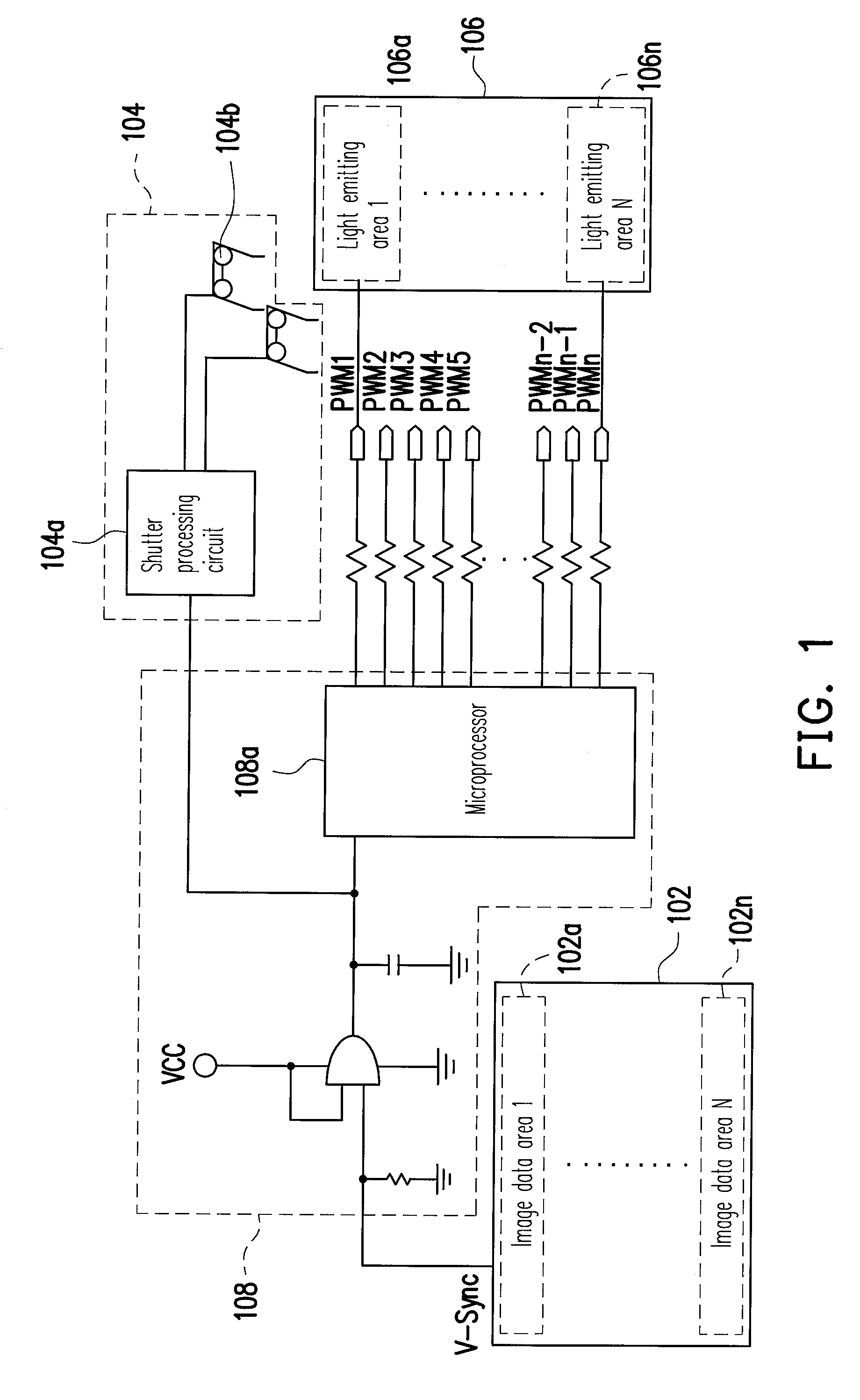
[0029]FIG. 3 is a diagram illustrating the driving clock of a stereo display according to an embodiment of the present invention. FIG. 4 is a diagram illustrating the driving of a display panel unit and a backlight unit in FIG. 3. First, referring to FIG. 3, in the present embodiment, a right eye image RF and a left eye image LF are alternatively or sequentially displayed in the display panel unit 102, and each image (the right eye image or the left eye image) is displayed for a time T. The display panel unit 102 generates a synchronizing vertical signal V-Sync during each image time T.
[0030]In addition, the clock signal of the right eye glass of the shutter glasses unit is RG, and the clock signal of the left eye glass of the shutter glasses unit is LG. Thus, when the display panel unit displays the right eye image RF, the clock signal RG of the right eye glass of the shutter glasses unit is in an on state, and the clock signal LG of the left eye glass of the shutter glasses unit i...
second embodiment
[0035]FIG. 5 is a diagram illustrating the driving clock of a stereo display according to another embodiment of the present invention. Referring to FIG. 5, in the present embodiment, the clock signals RG and LG for controlling the display panel unit 102 to display images according to the synchronizing vertical signal V-Sync and the shutter glasses unit 104 to be turned on and off according to the synchronizing vertical signal V-Sync are the same as those in the embodiment illustrated in FIG. 3 therefore will not be described herein. The difference between the present embodiment and the embodiment in FIG. 3 falls on the clock signal BL of the backlight unit. In the present embodiment, the light emitting areas of the backlight unit 106 are turned on simultaneously instead of sequentially. Namely, all the light emitting areas (the N light emitting areas) of the backlight unit 106 are turned on at the same time, and all the light emitting areas (the N light emitting areas) of the backli...
third embodiment
[0040]FIG. 7 is a diagram illustrating the driving clock of a stereo display according to still another embodiment of the present invention. Referring to FIG. 7, in the present embodiment, the clock signals RG and LG for controlling the display panel unit to display images according to the synchronizing vertical signal V-Sync and the shutter glasses unit to be turned on and off according to the synchronizing vertical signal V-Sync are the same as those in the embodiment illustrated in FIG. 3 therefore will not be described herein. The difference between the present embodiment and the embodiment in FIG. 3 is that in the present embodiment, the clock signal BL of the backlight unit 106 further includes an additional backlight clock signal BL0 besides the clock signal BL1 of the first light emitting area, the clock signal BL2 of the second light emitting area, the clock signal BL3 of the third light emitting area, and the clock signal BL4 of the fourth light emitting area. In other wor...
PUM
 Abstract
Description
Claims
Application Information
 - R&D
- Intellectual Property
- Life Sciences
- Materials
- Tech Scout
- Unparalleled Data Quality
- Higher Quality Content
- 60% Fewer Hallucinations
Browse by: Latest US Patents, China's latest patents, Technical Efficacy Thesaurus, Application Domain, Technology Topic, Popular Technical Reports.
© 2025 PatSnap. All rights reserved.Legal|Privacy policy|Modern Slavery Act Transparency Statement|Sitemap|About US| Contact US: help@patsnap.com


