Gas-Generator Augmented Expander Cycle Rocket Engine

a rocket engine and expansion cycle technology, applied in the field of rocket engines, can solve the problems of reducing the structural strength of the combustion chamber wall material, limiting the amount of available power to drive the turbomachinery, and engine with extremely high performance but also a high degree of complexity

Inactive Publication Date: 2010-02-04
NASA
View PDF19 Cites 24 Cited by
  • Summary
  • Abstract
  • Description
  • Claims
  • Application Information

AI Technical Summary

Benefits of technology

[0025]The present invention provides an improvement over the standard expander cycle engine by including a gas-generator and a close-coupled heat exchanger. The present invention also provides a significant improvement over the pre-burner system as disclosed in Hewitt because by completely decoupling two combustion zones, there is no delicate balance of performance between the two combustion zones. Due to the fact that in the present invention the gas-generator is not directly coupled to the turbomachinery, the possibility that combustion products, specifically steam, can get trapped in the turbomachinery components and preclude the possibility of ice forming in the turbomachinery prior to a subsequent restart of the engine, (which is a potentially catastrophic event) is practically eliminated.
[0026]According to a first aspect of the invention, there are two turbopumps, one for liquid hydrogen (for use as a fuel) and one for liquid oxygen (for use as an oxidizer). There is also a thrust chamber assembly within which the primary combustion takes place in order to provide the propulsive discharge of gases. The thrust chamber assembly is made in a manner allowing for fuel to flow interior to the wall, either via tubes or milled channels, thereby providing cooling.
[0028]According to the invention, the gas-generator is ignited first, prior to the main combustion chamber, immediately causing heat to be imparted to the coolant hydrogen. The result is that power is more quickly and assuredly delivered to the two turbopumps, thereby ensuring a smooth engine start transient. During regular operation, the gas-generator can be modulated to provide for various levels of engine thrust and can even be extinguished so the engine can function like a typical expander cycle if so desired. For example, a control module (not shown) provides, upon a start or restart, an actuation sequence in which the gas-generator fuel valve and the gas-generator oxidizer valve are actuated open prior to opening the coolant control valve, main fuel valve and main oxidizer valve for igniting the gas-generator prior to igniting the primary combustion chamber. This ignition sequence ensures a smooth engine start transient
[0030]In addition, the invention may include a secondary, smaller nozzle to discharge the gas-generator gases, instead of discharging them though the aft end of the first nozzle. The use of a secondary nozzle can provide the function of a settling motor, by using the ignition, initial burning and discharge from the gas-generator as the stage settling thrust, as a small amount of initial thrust is needed to locate the propellants in the proper manner when the engine is started in the zero-acceleration state.

Problems solved by technology

The result is an engine with extremely high performance but also a high degree of complexity.
Some disadvantages of all of the aforementioned expander cycle engines includes a limit in the amount of available power to drive the turbomachinery because the driving of the turbomachinery is caused by using the heat extracted through the cooling wall of the primary combustion chamber.
However, to design a thinner wall or increase the wall temperature causes a reduction of the structural strength of the combustion chamber wall material, thereby reducing the reliability of the component and the engine.
Also, typically such engines are shutdown fuel-rich, meaning that the through cooling passages permit cryogenic hydrogen to flow during the shutdown process.
However, when this practice is performed in outer space, the hardware and the passages can stay very cold for a long time.
Due to the fact that the expander cycle requires heat to initiate and drive the cycle, restarting the engine in this cold state is difficult and unreliable, as it will take some time before the engine has become warm enough to initiate the start sequence.
However Hewitt has disadvantages because the primary and secondary combustion zones are so closely linked.
Due to the fact that Hewitt effectively incorporates a staged-combustion element within the expander cycle, this inherently brings into the situation the difficult balancing act of the interplay between the two combustion zones.
Hewitt also suffers from some of the disadvantages of the other engines as well.
Other drawbacks of any of the above-mentioned rocket engines, including Hewitt, include the problem that after the engine is shut down, the residual combustion products, specifically steam, can freeze in the injectors and cause damage.
Moreover, for those engine cycles using combustion products as the turbine drive gas, the steam can also freeze in the turbomachinery, which has the potential to be even more disastrous upon attempted engine restart than the potential damage from steam freezing in the injectors.

Method used


Image

  • Gas-Generator Augmented Expander Cycle Rocket Engine
  • Gas-Generator Augmented Expander Cycle Rocket Engine
  • Gas-Generator Augmented Expander Cycle Rocket Engine

Examples


Embodiment Construction

[0035]The descriptions provided herein in accordance with the drawings have been provided for purposes of illustration and not for limitation. A person of ordinary skill in the art understands and appreciates that there are many variations of the present invention not shown that do not depart from the spirit of the invention and the scope of the appended claims.

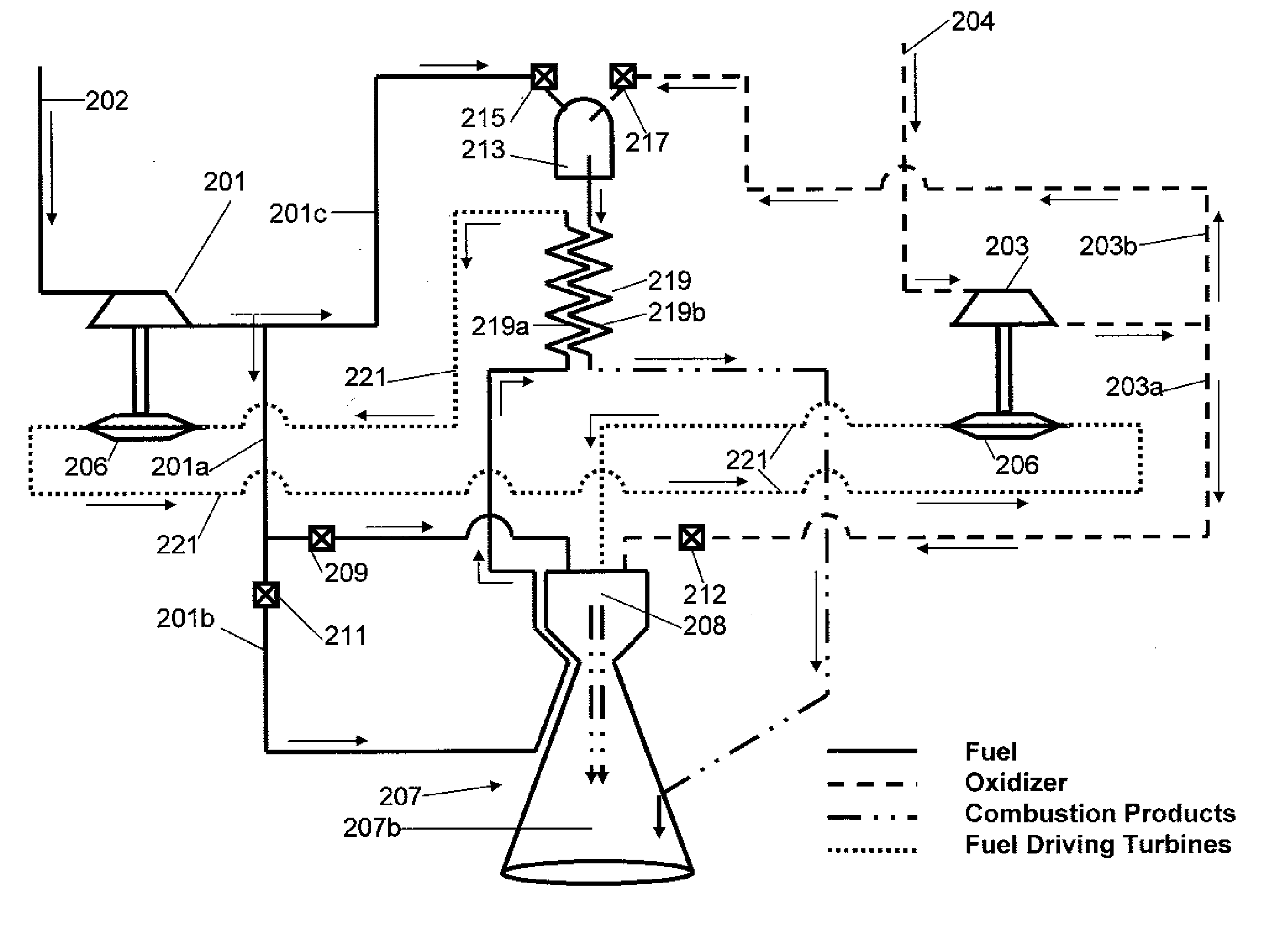
[0036]FIG. 4A is a simplified view of a first embodiment of a gas-generator augmented rocket engine according to the present invention. A person or ordinary skill in the art understands that the flow circuit shown in FIG. 4A is simplified so as not to obscure the invention with unnecessary detail. There are also a number of valves, ancillary lines, and by-pass pathways most of which are not shown on the diagram, but could typically be included. FIG. 4B uses the same reference numerals except they are increased by 1000, and indicates the same components as their counterparts in FIG. 4A, except for the second nozzle, which is d...


PUM


Abstract

An augmented expander cycle rocket engine includes first and second turbopumps for respectively pumping fuel and oxidizer. A gas-generator receives a first portion of fuel output from the first turbopump and a first portion of oxidizer output from the second turbopump to ignite and discharge heated gas. A heat exchanger close-coupled to the gas-generator receives in a first conduit the discharged heated gas, and transfers heat to an adjacent second conduit carrying fuel exiting the cooling passages of a primary combustion chamber. Heat is transferred to the fuel passing through the cooling passages. The heated fuel enters the second conduit of the heat exchanger to absorb more heat from the first conduit, and then flows to drive a turbine of one or both of the turbopumps. The arrangement prevents the turbopumps exposure to combusted gas that could freeze in the turbomachinery and cause catastrophic failure upon attempted engine restart.

Description

ORIGIN OF THE INVENTION[0001]This invention was made by an employee of the United States Government and may be manufactured and used by or for the Government for governmental purposes without the payment of any royalties.BACKGROUND OF THE INVENTION[0002]1. Field of the Invention[0003]The present invention relates to rocket engines. More particularly, the invention relates to upper stage, restart capable, highly reliable rocket engines.[0004]2. Discussion of the Related Art[0005]Launch vehicles are typically comprised of multiple elements stacked together in stages. There are lower stages and upper stages, with the lower stages being used for lifting the most weight and pushing a vehicle through the thicker layers of lower atmosphere. The upper stages normally fire subsequent to the vehicle traveling very fast in thinner layers of atmosphere and at a very high rate of speed. Accordingly, improvements in upper stage rocket design, even relatively minor improvement can provide a large ...

Claims


Application Information

Patent Timeline
Patent Type & Authority Applications(United States)
IPC IPC(8): F02K9/64F02K9/46
CPCF02K9/42F02K9/48F02K9/52F05D2240/40F02K9/64F02K9/972F02K9/58
Inventor GREENE, WILLIAM D.
Owner NASA
Why Eureka
Try Eureka