Image recording apparatus, image recording method and image recording program
a technology of image recording and recording method, applied in the field of image recording apparatus, image recording method and image recording program, can solve the problems of difficult to quickly retrieve the region and difficult to capture an imag
- Summary
- Abstract
- Description
- Claims
- Application Information
AI Technical Summary
Benefits of technology
Problems solved by technology
Method used
Image


Examples
first embodiment
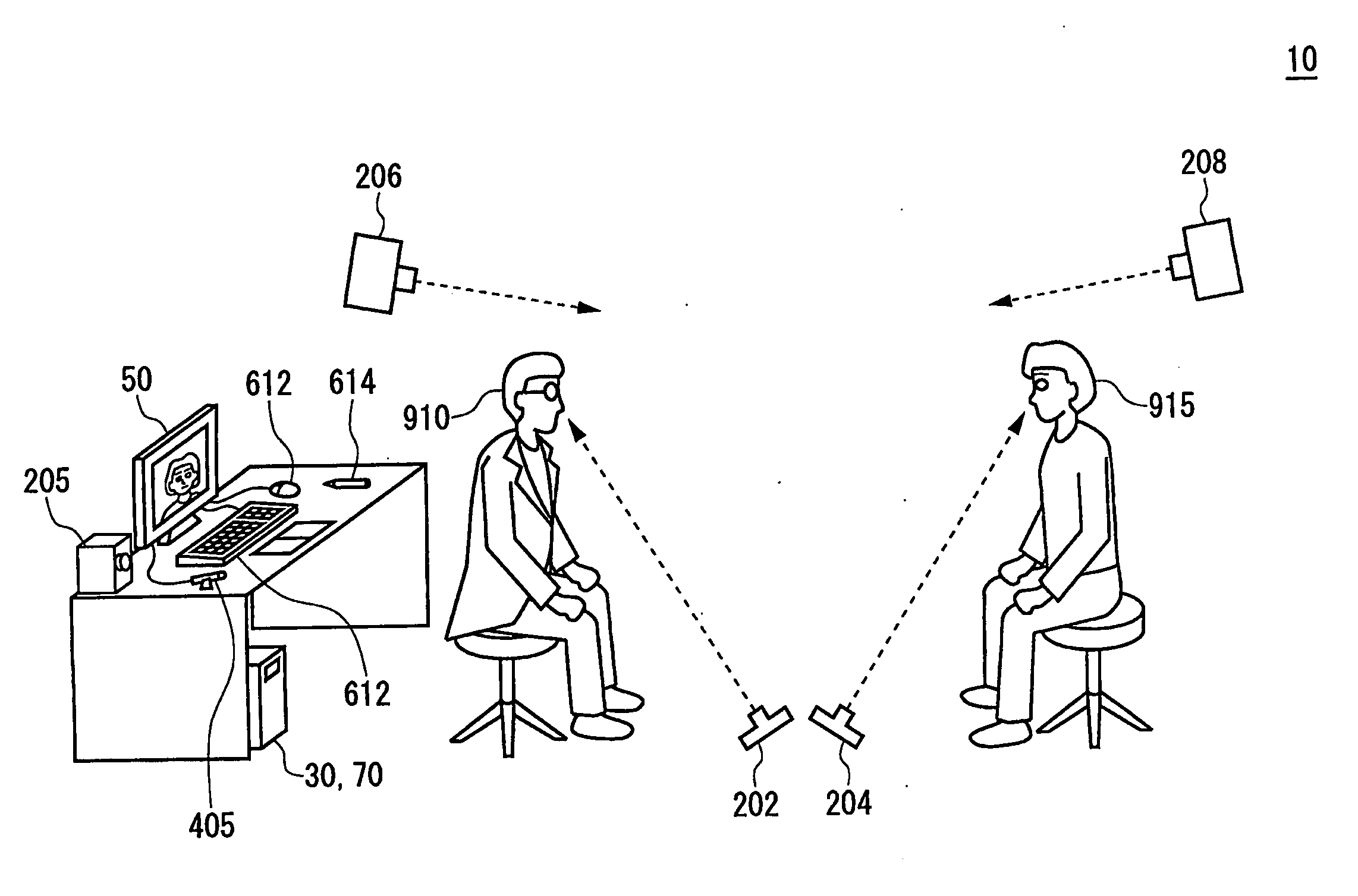
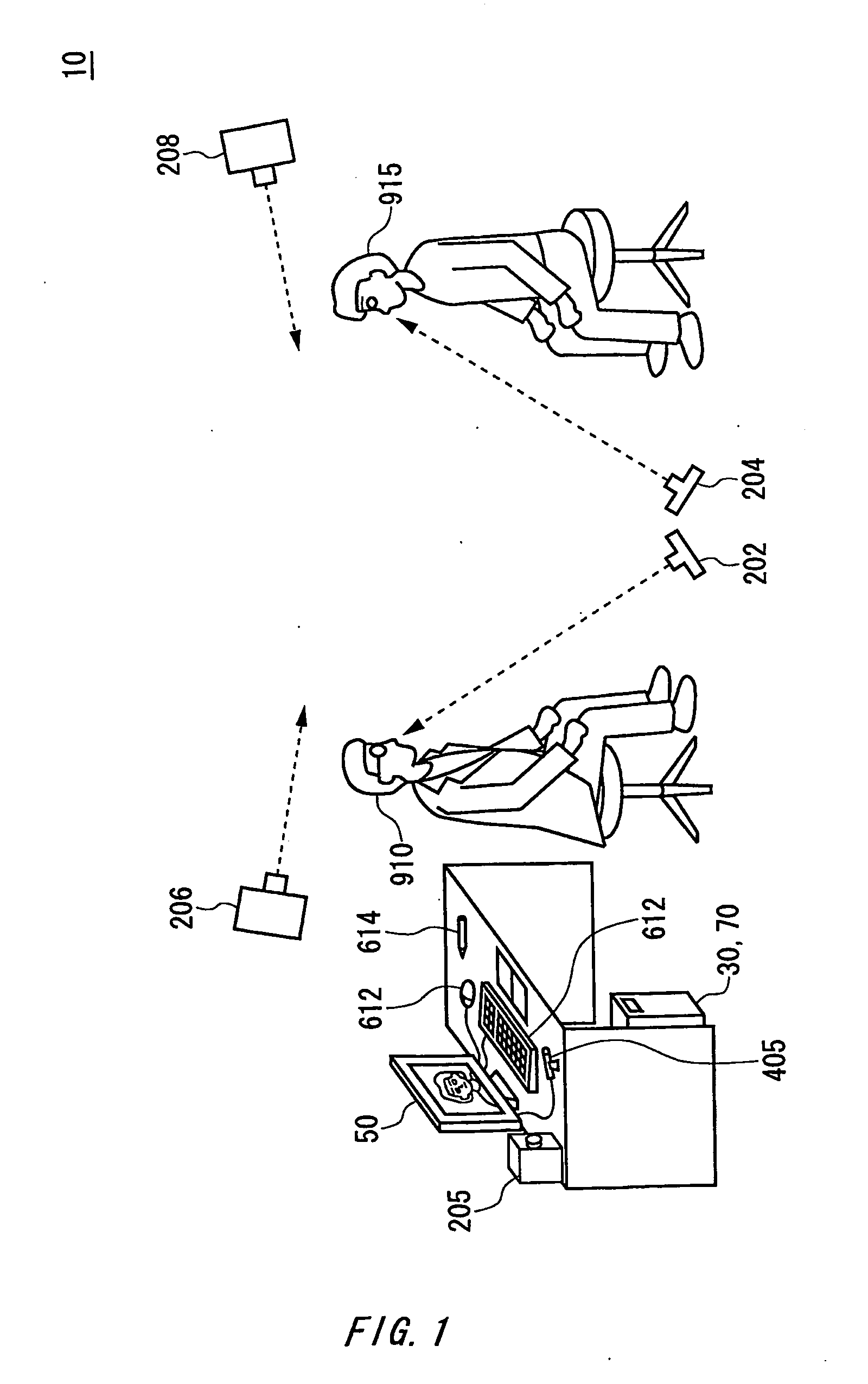
[0054]According to the image recording apparatus 10 of the first embodiment, the point of sight of the observer 910 can be overlapped onto the image of the observed person 915 when displayed. In this way, the image recording apparatus 10 makes it possible to easily know the area of the observed person 915 on which the observer 910 focuses while observing the observed person 915. For example, a moving image of the observed person 915 can be captured and displayed on the output section 50 with the movement of the point of sight of the observer 910 being overlapped onto the moving image. Therefore, the image recording apparatus 10 can reproduce how the observer 910 observes and diagnoses the observed person 915. Also, the image recording apparatus 10 can capture an image showing how the observed person 915 behaves while the observer 910 writes the result of the observation into the electronic medical record. In this way, even if the observer 910 misses a change in the facial expression...
second embodiment
[0097]FIG. 12 illustrates an exemplary functional configuration of the image-capturing unit 20 relating to a The image-capturing unit 20 relating to the present embodiment includes therein an image-capturing section 200, the observer's point of sight measuring section 210, the observed person's position measuring section 212, the observed person's point of sight measuring section 214, a point of sight moving method learning section 216, the observer's point of sight judging section 250, a point of sight moving method storing section 255, and an image storing control section 260. The present embodiment provides an image recording apparatus for accurately recording the change in the facial expressions of the observed person 915 during conversation. The image-capturing unit 20 relating to the present embodiment may further include some or all of the functions and constituents of the units which together constitute the image recording apparatus 10 described with reference to FIGS. 1 to...
fifth embodiment
[0160]FIG. 26 illustrates an exemplary functional configuration of the image-capturing unit 50 relating to a The image-capturing unit 20 includes therein the image-capturing section 200, observer's point of sight measuring section 210, observed person's position measuring section 212, observed person's point of sight measuring section 214, observer's point of sight judging section 250, image storing control section 260, observer's position measuring section 270, and a line of sight coincidence judging section 280. The following description is made based on an assumption that the image recording apparatus 10 relating to the present embodiment is used in the medical field. The image recording apparatus 10 relating to the present embodiment quantifies the physical status of the observed person 915 when the observer 910 observes the observed person 915, and records thereon the quantified physical status. Based on this, the image recording apparatus 10 relating to the present embodiment...
PUM
 Abstract
Description
Claims
Application Information
PatSnap Eureka turns technology decisions into work you can execute. Powered by our Innovation Knowledge Graph, it runs expert workflows across engineering, life sciences, materials and intellectual property. Get your review-ready output in minutes.


