Dynamic Highlighting of Related Artifacts in a UML Diagram

a technology of related artifacts and uml diagrams, applied in the field of hierarchical diagrams, can solve the problems of cumbersome viewing and editing of activity diagrams containing a large number of objects, current uml tooling does not provide a particularly easy way to display complex uml diagrams, and the system is not currently availabl

Active Publication Date: 2010-02-11
IBM CORP
View PDF10 Cites 19 Cited by
  • Summary
  • Abstract
  • Description
  • Claims
  • Application Information

AI Technical Summary

Problems solved by technology

However, these current UML design tools are focused on system design and are not integrated with a class browser.
Thus, current UML tooling does not provide a particularly easy way to display complex UML diagrams.
Activity diagrams that consist of a large number of objects can be cumbersome to view and edit.
Complex diagrams can be split into smaller diagrams showing just the relevant objects; however, a system is not currently available that can display all the objects in a way that is easy to use.

Method used


Image

  • Dynamic Highlighting of Related Artifacts in a UML Diagram
  • Dynamic Highlighting of Related Artifacts in a UML Diagram
  • Dynamic Highlighting of Related Artifacts in a UML Diagram

Examples


Embodiment Construction

[0021]The embodiments of the invention and the various features and advantageous details thereof are explained more fully with reference to the non-limiting embodiments that are illustrated in the accompanying drawings and detailed in the following description. It should be noted that the features illustrated in the drawings are not necessarily drawn to scale. Descriptions of well-known components and processing techniques are omitted so as to not unnecessarily obscure the embodiments of the invention. The examples used herein are intended merely to facilitate an understanding of ways in which the embodiments of the invention may be practiced and to further enable those of skill in the art to practice the embodiments of the invention. Accordingly, the examples should not be construed as limiting the scope of the embodiments of the invention.

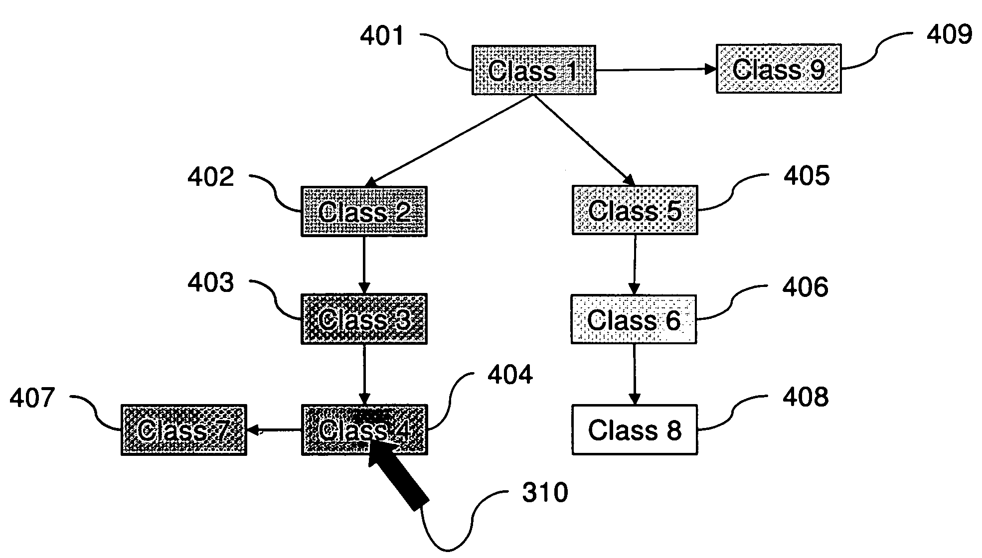
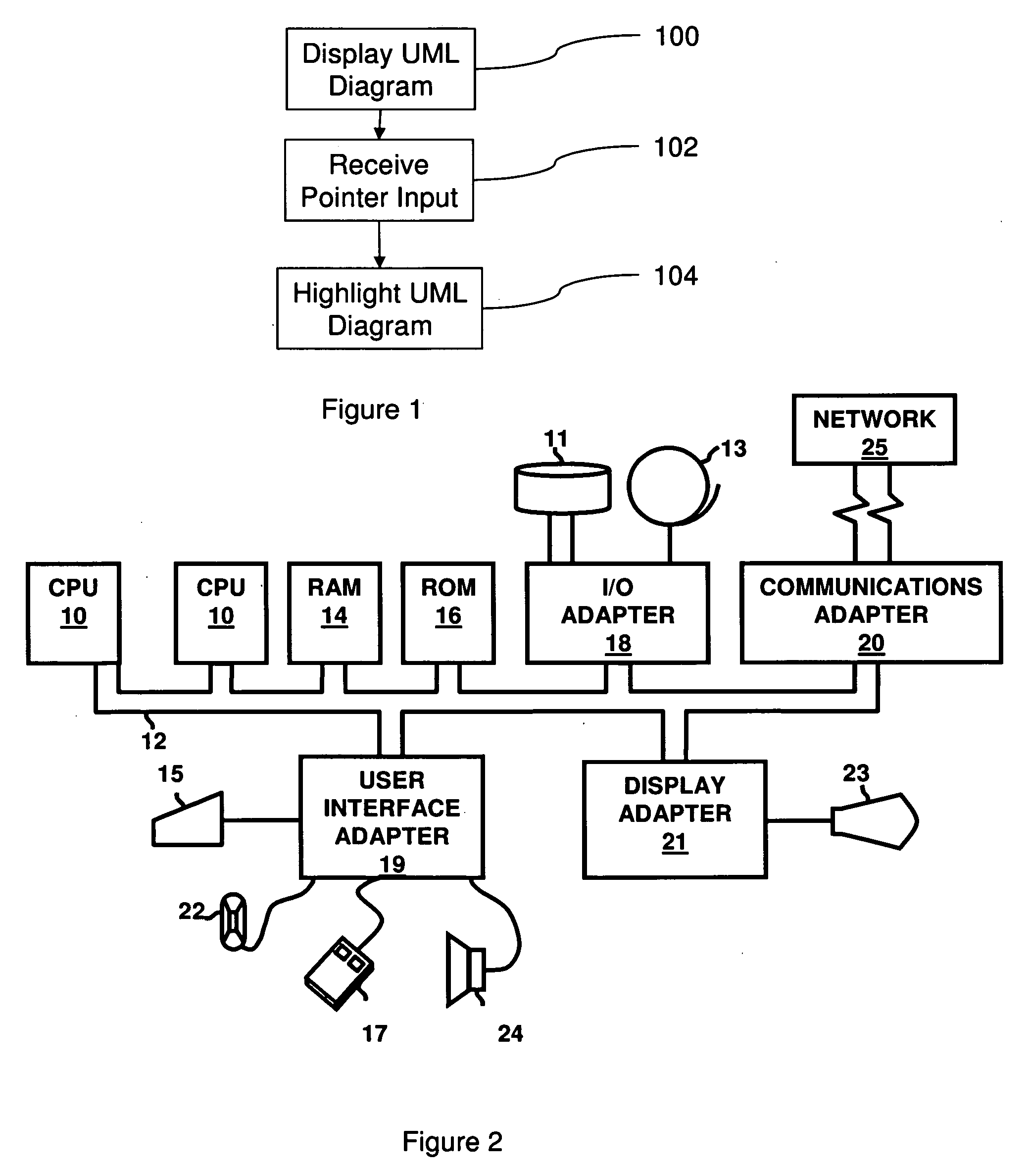
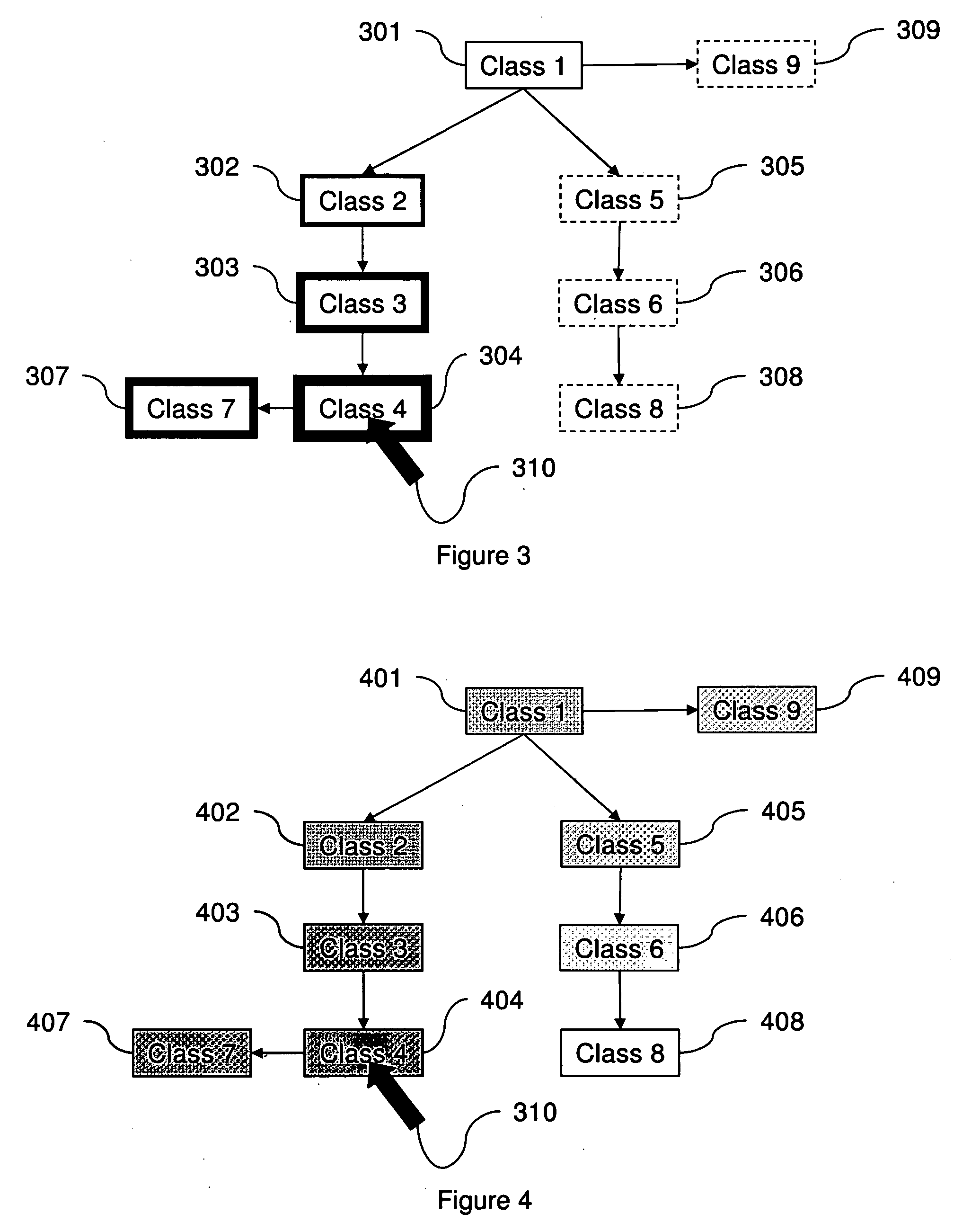
[0022]As mentioned above, there is a need to simplify the display of UML diagrams. Therefore, presented herein are system, method, and computer ...


PUM


Abstract

A method displays a Unified Modeling Language (UML) diagram on a graphic user interface. The UML diagram can have, for example, nodes representing objects of an object-oriented system. Further, input is received regarding the location of a user-directed pointer on the UML diagram. The location of the pointer identifies a currently “selected node” of the UML diagram. In response to such input, the method dynamically highlights portions of the UML diagram depending on the location of the selected node. This highlighting process dynamically alters the appearances of nodes logically related to the selected node by highlighting nodes that are relatively closely related to the selected node differently (e.g., more brightly) than nodes that are not as relatively closely related to the selected node.

Description

BACKGROUND[0001]1. Field of the Invention[0002]The embodiments of the invention generally relate to displaying hierarchical diagrams and more particularly to providing an improved interface with a hierarchical diagram through the use of dynamic highlighting.[0003]2. Description of Related Art[0004]In an object oriented development environment, software applications are developed as a set of objects and classes that interact with one another. Thus, application developers and other users are required to understand complex relationships between components of software systems in order to develop, implement, and maintain such systems. In order to better understand the relationships between objects and their classes, a number of current development tools provide a class browser that allows navigating between the individual classes of a software system or application.[0005]A current technology for understanding complex object oriented software systems is the Unified Modeling Language (UML)...

Claims


Application Information

Patent Timeline
Patent Type & Authority Applications(United States)
IPC IPC(8): G06F9/44
CPCG06F8/33
Inventor LIMBURN, JONATHAN J.
Owner IBM CORP
Why Eureka
Try Eureka