System and Method for Image Projection of Operator Data From An Operator Control Unit

a technology of operator control and image projection, which is applied in the field of system and method for imaging data, can solve the problems of notably slow transmission speed of information to the ocu, data conveyable to the operator is typically limited to functional language, and the delivery of information to the lcd is particularly affected

Inactive Publication Date: 2010-02-18
GENERAL ELECTRIC CO
View PDF9 Cites 23 Cited by
  • Summary
  • Abstract
  • Description
  • Claims
  • Application Information

AI Technical Summary

Benefits of technology

[0005]One embodiment of the present invention provides a system for viewing information associated with a locomotive or other vehicle. The system includes an imaging device configured to collect and transmit one or more visual images of a portion of the locomotive or other vehicle or an area surrounding the locomotive. The system further includes an off-board operator control unit configured to receive the one or more visual images from the imaging device. In addition, the operator control unit comprises a projector configured to project the received one or more images onto a substrate. By “substrate,” it is meant a surface capable of receiving a projected image for viewing the content of the projected image. Also, by “off-board,” it is meant that the operator control unit is not on the locomotive or other vehicle.
[0006]Another embodiment of the present invention provides a system for viewing information in a rail yard or other location where vehicles are marshaled, organized, switched, or dispatched. The system includes a dispatcher for s

Problems solved by technology

One problem associated with known OCU devices, particularly ones having LCD displays, is that the data conveyable to the operator is typically limited to functional language.
Moreover, it is known that the delivery of information to the LCD is particularly affected by cold weather.
In such an environment, the speed of transmission to the OCU may be notably slow.
Moreover, in especially

Method used


Image

  • System and Method for Image Projection of Operator Data From An Operator Control Unit
  • System and Method for Image Projection of Operator Data From An Operator Control Unit
  • System and Method for Image Projection of Operator Data From An Operator Control Unit

Examples


Embodiment Construction

[0019]In describing particular features of different embodiments of the present invention, number references will be utilized in relation to the figures accompanying the specification. Similar or identical number references in different figures may be utilized to indicate similar or identical components among different embodiments of the present invention.

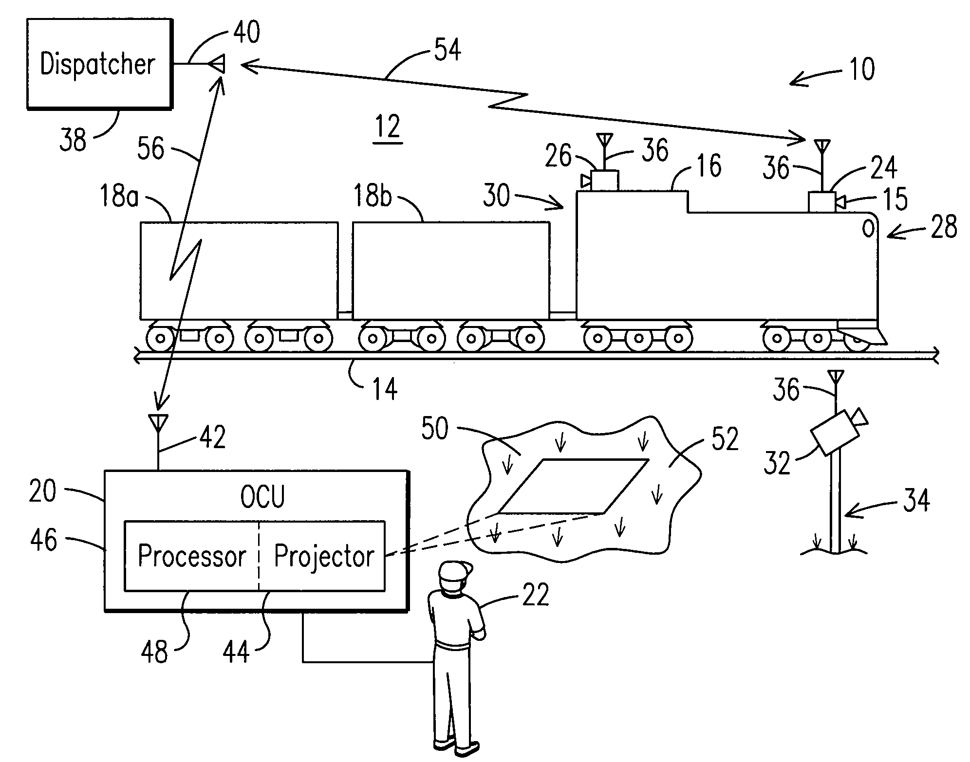
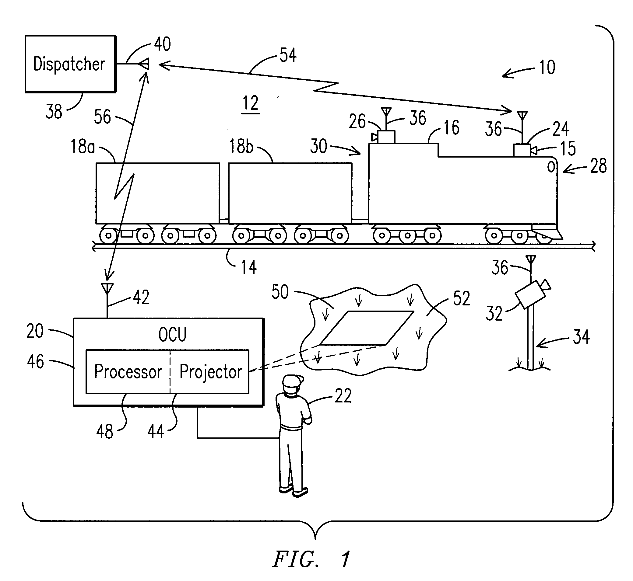
[0020]Now referring to the figures, FIG. 1 illustrates an embodiment of a system 10 for imaging data in a typical train depot or rail yard 12. As will be appreciated by those skilled in the art, the rail yard 12 may comprise a large number of interconnectable railtracks 14, which are connectable through the activation of switches (not shown) to a suitable switching state. In the embodiment shown, the system 10 includes a train having a locomotive 16 and a plurality of train cars 18a, 18b connected thereto, an imaging device 15 located on or about the locomotive 16, and an Operator Control Unit (OCU) 20, typically held by an operato...


PUM


Abstract

A system is provided for projecting images of operator data from an operator control unit. The system includes an imaging device configured to collect and transmit one or more visual images of a portion of a locomotive (or other vehicle) or an area surrounding the locomotive. In addition, the system includes an off-board operator control unit configured to receive the one or more visible images from the imaging device and comprising a projector configured to project the received one or more images onto a substrate. Additionally, a method for projecting images of operator data from an operator control unit is provided.

Description

FIELD OF THE INVENTION[0001]The present invention relates to a system and method for imaging data, and more particularly, to a system and method for projecting images of operator data from an operator control unit.BACKGROUND OF THE INVENTION[0002]Classification yards are used in rail transportation environments to sort freight cars onto different track sections depending on each freight car's destination after leaving the yard. Yard switching refers to the transfer of a freight car or freight cars from one track to another within the yard, typically with the intent of assembling a train bound for a common destination. In the past, the switching of trains in a rail yard required a “switchman” on the ground at each end of the train to properly align the tracks and an engineer in a cab of a locomotive of the train in communication with the switchman for moving the train down the desired tracks according to the switchman's instructions. More recently, locomotives equipped with remote co...

Claims


Application Information

Patent Timeline
IPC IPC(8): H04N7/18G06F17/00H04N9/31G01C21/00
CPCB61L3/127H04N7/181B61L23/041
Inventor BRAND, JOHN
Owner GENERAL ELECTRIC CO
Why Eureka
Try Eureka