Automated control system for back-reaming

a control system and back-reaming technology, applied in the field of automatic control systems, can solve the problems that many hoisting systems cannot tolerate holding drill pipes without movement, and the pipe may be in danger of jamming, so as to reduce the speed of hoisting

Active Publication Date: 2005-07-19
VARCO I P INC
View PDF5 Cites 16 Cited by
  • Summary
  • Abstract
  • Description
  • Claims
  • Application Information

AI Technical Summary

Benefits of technology

[0008]The present invention is directed to a control system for the automated operation of a drawworks during a “back reaming” operation. In one embodiment the control system is connected to an operator control unit to allow a driller to enter maximum values to be reached during the reaming operation for one or more specified reaming parameters. During the reaming operation, the control system continuously monitors the specified reaming parameters and compares the measured values to the limits or maximum values input by the operator. When any of the maximum values are exceeded, a control signal is sent to the drawworks to reduce the speed of the hoisting.

Problems solved by technology

However, during this operation, the driller must simultaneously monitor the hookload, and the rotating torque or standpipe pressure (if using a downhole mud motor) for indications that the pipe is in danger of jamming in a lateral direction or a rotational direction, respectively.
However, the driller must still monitor the hookload, the rotating torque and / or the standpipe pressure for indications of that the drill pipe may be in danger of jamming in the borehole.
In addition, a problem with both of these processes is that many hoisting systems cannot tolerate holding a drill pipe without movement for an extended period of time, a situation that can occur when a drill pipe does jam in the borehole.

Method used


Image

  • Automated control system for back-reaming
  • Automated control system for back-reaming
  • Automated control system for back-reaming

Examples


Embodiment Construction

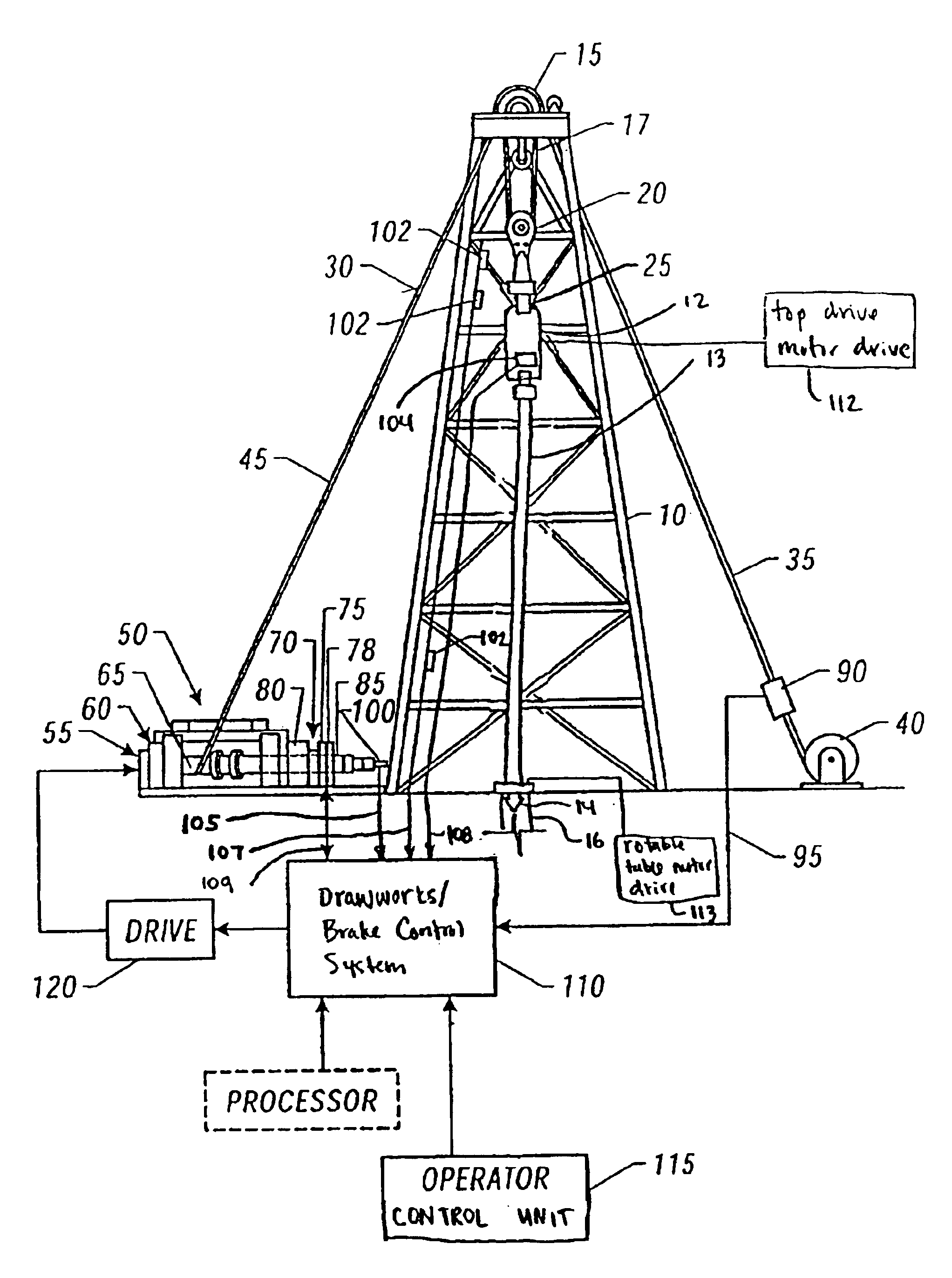
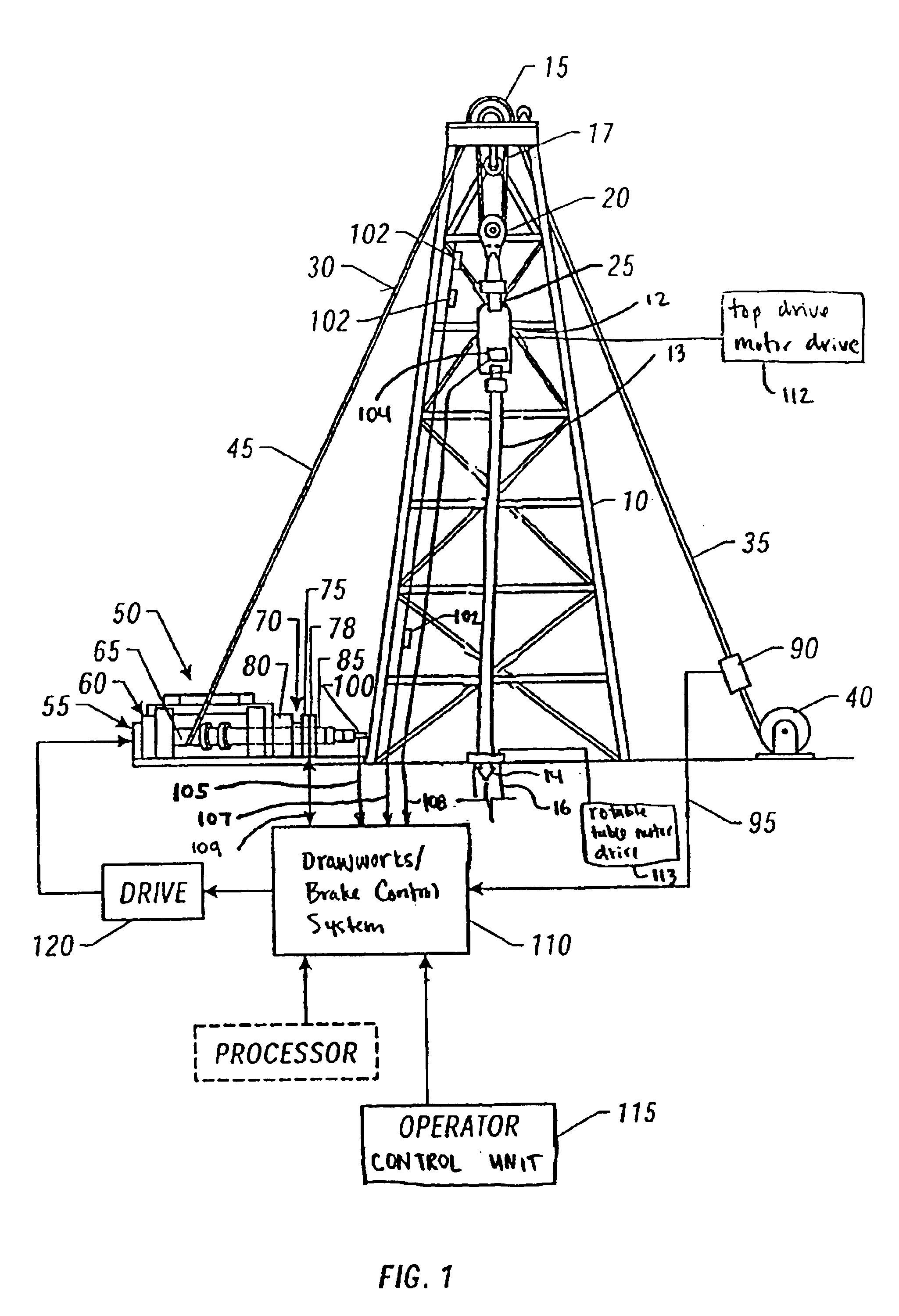
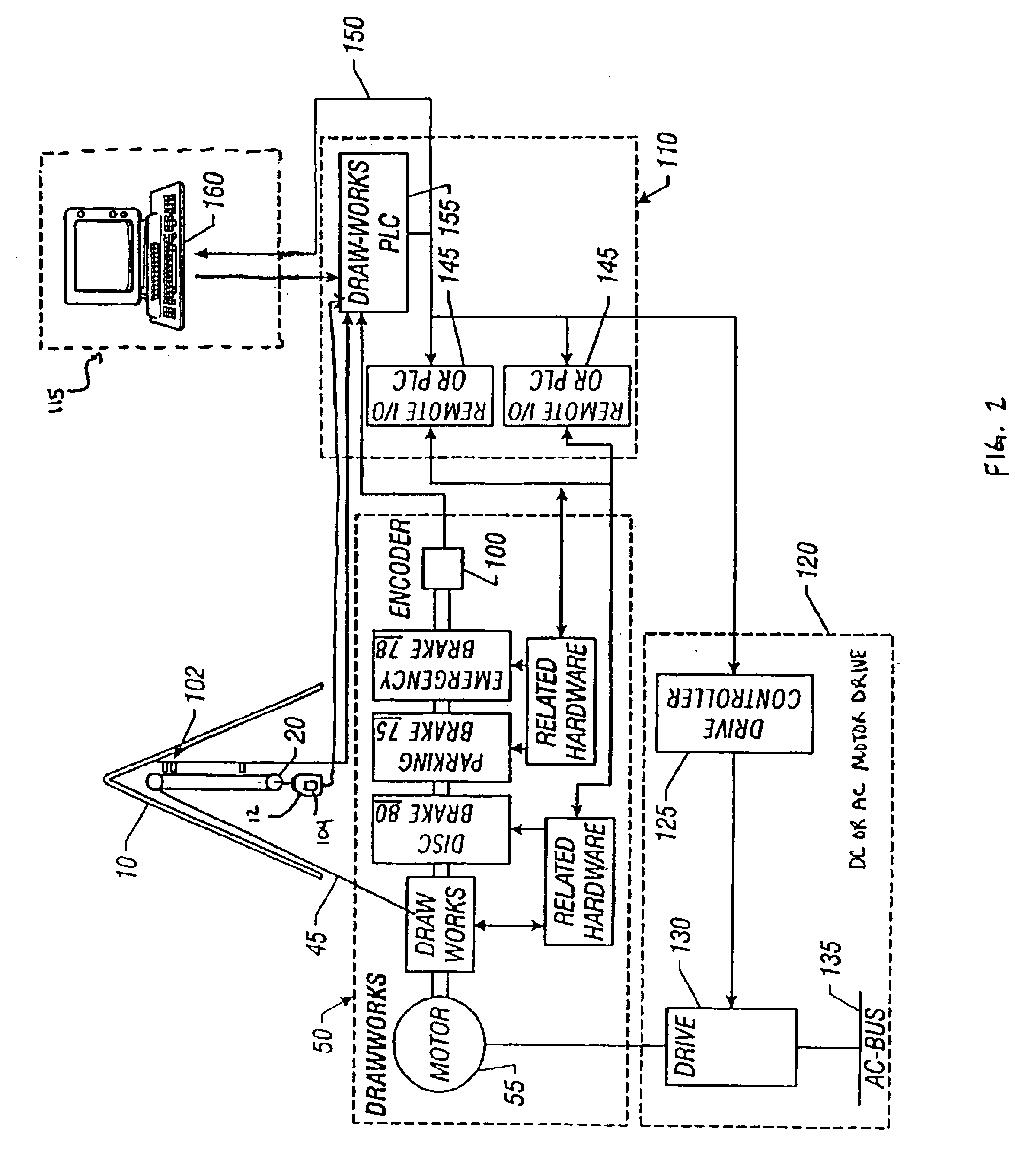
[0017]As shown in FIGS. 1-3, the invention is directed to a drawworks / brake control system 110 (hereinafter “control system 110”) for the automated operation of a drawworks 50 or similar hoisting means during a “back reaming” (hereinafter “reaming”) operation.

[0018]As shown in FIG. 1, in one embodiment of the current invention the control system 110 is connected to an operator control unit 115. A driller or operator enters into the control unit 115 maximum values to be reached during the reaming operation for one or more specified reaming parameters. For example, the reaming parameters may include any or all of the pull on the drill bit (POB), the rate of hoisting (ROH), and the drilling torque. The operator then initiates the reaming operation.

[0019]During the reaming operation, the control system 110 continuously monitors the POB, ROH and / or the drilling torque through various sensors 90, 100 and 104, and compares the measured values to the limits or maximum values input by the op...


PUM


Abstract

A system that controls a back reaming operation of a drilling rig is provided that includes a hoisting system that moves a drill pipe during a back reaming operation at a hoisting speed and a hoisting torque. The hoisting system comprises at least one back reaming parameter sensor for measuring a corresponding at least one back reaming parameter. An operator control unit allows an operator to input a predetermined value of the at least one back reaming parameter therein. A back reaming parameter sensor obtains the measured value of the at least one back reaming parameter. A control system monitors the at least one back reaming parameter. A braking assembly resists the hoisting torque of the drawworks system when the measured value of the at least one back reaming parameter equals the predetermined value of the at least one back reaming parameter.

Description

CROSS-REFERENCE TO RELATED APPLICATION(S)[0001]This application claims priority under 35 U.S.C. §119(e) to U.S. Provisional Application Ser. No. 60 / 447,984, filed on Feb. 15, 2003, which is incorporated herein by reference.FIELD OF THE INVENTION[0002]The present invention relates to an automated control system for operating a drawworks or similar hoisting means during a back reaming operation.BACKGROUND OF THE INVENTION[0003]In the petroleum industry, the apparatus and machinery used to drill wells is commonly known as a drilling rig or a rig. On these rigs are means of rotating the drill pipe, the most popular and successful of which is a device known as a top drive system. The popularity and proliferation of top drive systems within the oilfield has greatly enhanced the capability of the industry's drillers and operators to handle drill pipe operations in safe and beneficial manners.[0004]One such operation is “back reaming” wherein the operator hoists a drill pipe out of a boreho...

Claims


Application Information

Patent Timeline
Patent Type & Authority Patents(United States)
IPC IPC(8): E21B44/00E21B44/04E21BE21B19/00E21B19/02E21B19/08E21B44/02
CPCE21B19/008E21B19/02E21B19/08E21B44/00E21B44/02E21B44/04
Inventor PRIOR, BRUCEPORCHE, MIKE
Owner VARCO I P INC
Why Eureka
Try Eureka