Remote Monitoring And Munitions Deployment System

a technology applied in the field of remote monitoring and munitions deployment systems, can solve the problems of non-selective, lethal, wounding or killing non-combatants, and great international pressure to discontinue the use of such non-selective means of defens

Inactive Publication Date: 2010-04-15
JONES KENNETH R +2
View PDF7 Cites 22 Cited by
  • Summary
  • Abstract
  • Description
  • Claims
  • Application Information

AI Technical Summary

Benefits of technology

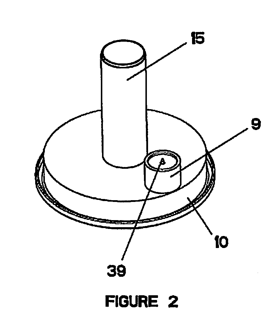
[0036]In a tenth embodiment of the present invention, the system for remotely monitoring an environment and selectively deploying munitions according to the first embodiment above is provided, further comprising adapter means capable of adapting the size of the munitions containment means to accommodate a munition having different dimensions than the munitions containment means. For example, where the munitions containment means is a slot which supports a round-shaped munition, an adapter is provided which can support fielded rounds, such as 40 mm grenades, and enable them to be fitted in the munitions containment means and properly interact with the munitions deployment device (so that they may be fired by the device). In particular, in addition to simply enabling munitions of different sizes to fit in the munitions containment means, the adapter may also be operable to identify the presence of a munition, the identity and characteristics of same, and relay this data to the munitions deployment means when queried.

Problems solved by technology

However, claymore style mines, being lethal or non-lethal, are able to provide merely one means of deterrent or defense after emplacement.
Thus, they are non-selective, lethal, and frequently wound or kill non-combatants.
Thus, there is currently great international pressure to discontinue the use of such non-selective means of defense.

Method used


Image

  • Remote Monitoring And Munitions Deployment System
  • Remote Monitoring And Munitions Deployment System
  • Remote Monitoring And Munitions Deployment System

Examples


Embodiment Construction

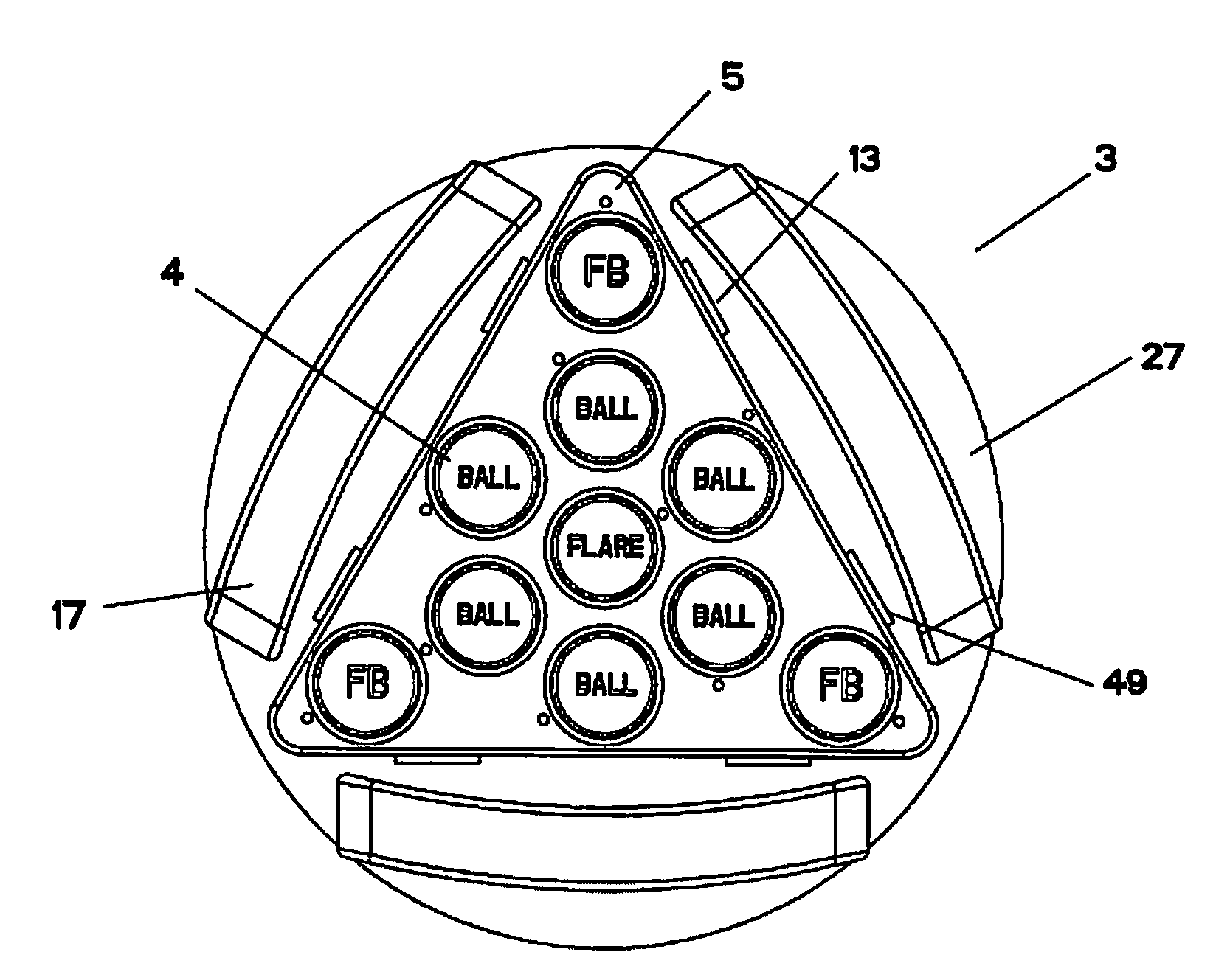
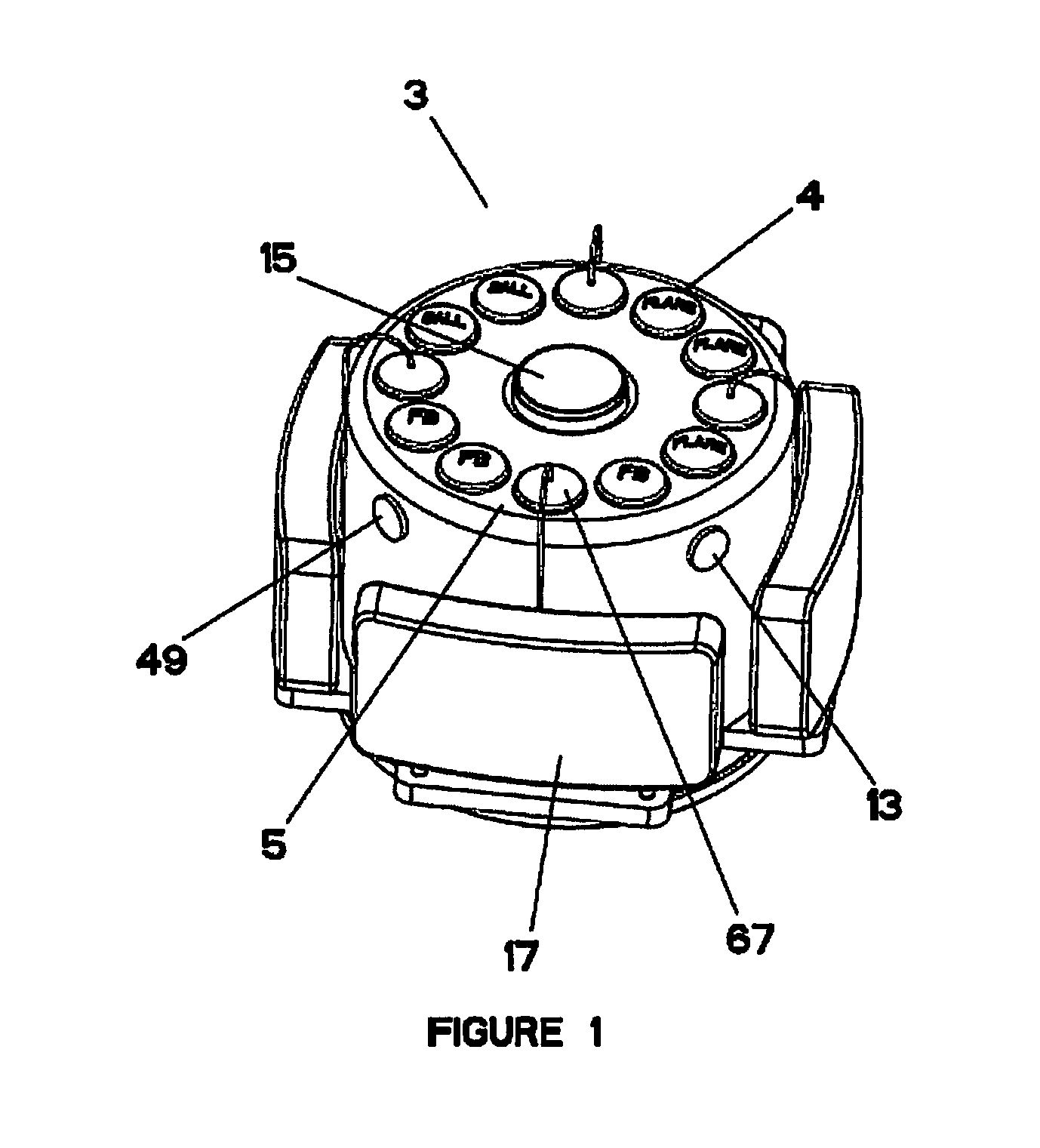
[0065]As called for in the first embodiment herein, and as illustrated in FIGS. 1 and 12, the present invention provides a system 1 for remotely monitoring an environment and selectively deploying munitions. In particular, as illustrated in FIG. 12, the system 1 of the present invention is comprised of one or more sensors 13 capable of monitoring selected environments, and one or more munitions deployment devices 3 disposed in the selected environment(s). These sensors 13 communicate data directly to an operator control unit (OCU) 11, or to the OCU via a munitions deployment device 3 or network bridge (not shown, but may be any conventional network bridge device). This sensor data is then communicated to a user via human-computer interface, such as any conventional graphical user interface (e.g., video screen), enabling a user to selectively deploy munitions disposed in or in communication with the munitions deployment device(s) 3 of the system 1. Deployable munitions 4 include, but...


PUM


Abstract

A system for remotely monitoring an environment and selectively deploying munitions is provided. The system is comprised of sensors to monitor one or more select environments, one or more munitions deployment devices disposed in the selected environment, and an operator control unit (OCU) operable to communicate with the munitions deployment device(s) and sensors. Sensor data is communicated to the system, enabling a user to selectively deploy munitions disposed in or in communication with the munitions deployment device(s), based on the threat detected by the sensors. Deployable munitions include both lethal and non-lethal munitions. The munitions deployment devices may be deployed in a stationary location, or in mobile applications, such as on a robotic vehicle, and accommodate removably, electrically initiated munitions cartridges. Further, the deployment devices may be in wired or wireless communication with the system, allowing virtually unlimited scalability.

Description

RELATED APPLICATION[0001]This is a nonprovisional application of copending corresponding provisional application Ser. No. 61 / 123, 301, filed Apr. 7, 2008, the contents of which are incorporated herein by reference.FIELD OF THE INVENTION[0002]A system capable of remotely monitoring an environment, such as a perimeter of a secure facility or a battlefield, via a stationary or mobile emplacement, and selectively deploying a lethal or non-lethal munition, is provided. In particular, a system enabling a user to monitor intrusion of a selected environment, and selectively deploy an appropriate munition based on the observed threat is provided. In addition, the system is operable to allow a user to escalate the response, e.g., from non-lethal to lethal means, based on changes in the perceived threat.BACKGROUND OF THE INVENTION[0003]Perimeter defense has traditionally been achieved by using remotely controlled, permanently disposed lethal munitions. For example, in military applications, cl...

Claims


Application Information

Patent Timeline
Patent Type & Authority Applications(United States)
IPC IPC(8): F41H11/00F41H13/00G06G7/80G06F19/00
CPCF41A23/12F41F1/08F41F7/00F42B12/207F42B39/26F42B12/365F42B12/42F42B12/46F42B23/10F42B12/32
Inventor JONES, KENNETH R.ULICKI, EDWARD M.DINDL, FRANK J.
Owner JONES KENNETH R
Why Eureka
Try Eureka