Fuel injector including a compound angle orifice disc for adjusting spray targeting

a fuel injector and compound angle technology, applied in the direction of spray nozzles, mechanical equipment, machines/engines, etc., can solve the problems of unsuitable orifice discs for their intended purposes, unsuitable orifice discs with structural unsuitability, and unsuitable orifice discs for their intended functions, so as to improve the ability to meet different, equivalent or improved consistency

Active Publication Date: 2005-11-03
VITESCO TECH USA LLC
View PDF36 Cites 11 Cited by
  • Summary
  • Abstract
  • Description
  • Claims
  • Application Information

AI Technical Summary

Benefits of technology

[0006] The present invention provides for an orifice disc with orifices oriented at an angle that is no longer exclusively related to a dimpling angle but is related to both an oblique angle at which the orifice is oriented relative to a base plane of the orifice disc and the dimpling angle. Thus, the present invention provides for a novel form of thin disc orifice members that can enhance the ability to meet different and / or more stringent demands with equivalent or even improved consistency. For example, certain thin disc orifice members according to the invention are well suited for engines in which a single fuel injector is required to direct sprays or stream to one or more intake valve; and thin disc orifice members according to the invention can satisfy difficult installations where space for mounting the fuel injector is severely restricted due to packaging constraints. It is believed that one of the advantages of the invention arises because the metering orifices are located in facetted planar surfaces. This has been found important in providing enhanced flow stability for proper interaction with upstream flow geometries internal to the fuel injector. The presence of a metering orifice in a non-planar surface, such as in a conical dimple, may not be able to consistently achieve the degree of enhanced flow stability that is achieved by its disposition on a facetted planar surface as in the present invention. The particular shape for the indentation that contains the facetted planar surfaces having the metering orifices further characterizes the present invention.

Problems solved by technology

Notwithstanding the potential increase in sac volume when the orifice disc is dimpled in order to obtain large values of bending and splitting spray angles, the disc material, in extreme cases, may shear between holes or at creases in the geometrical dimple, thereby rendering the orifice disc unsuitable to function as desired, such as, for example, metering fuel flow.
And depending on the physical properties of the material such as, for example, thickness and yield strength of the material, it is believed that there is an upper limit to the dimpling angle, as too great a dimpling angle can cause the material to shear, rendering the orifice disc structurally unsuitable for its intended purpose.

Method used


Image

  • Fuel injector including a compound angle orifice disc for adjusting spray targeting
  • Fuel injector including a compound angle orifice disc for adjusting spray targeting
  • Fuel injector including a compound angle orifice disc for adjusting spray targeting

Examples


Embodiment Construction

)

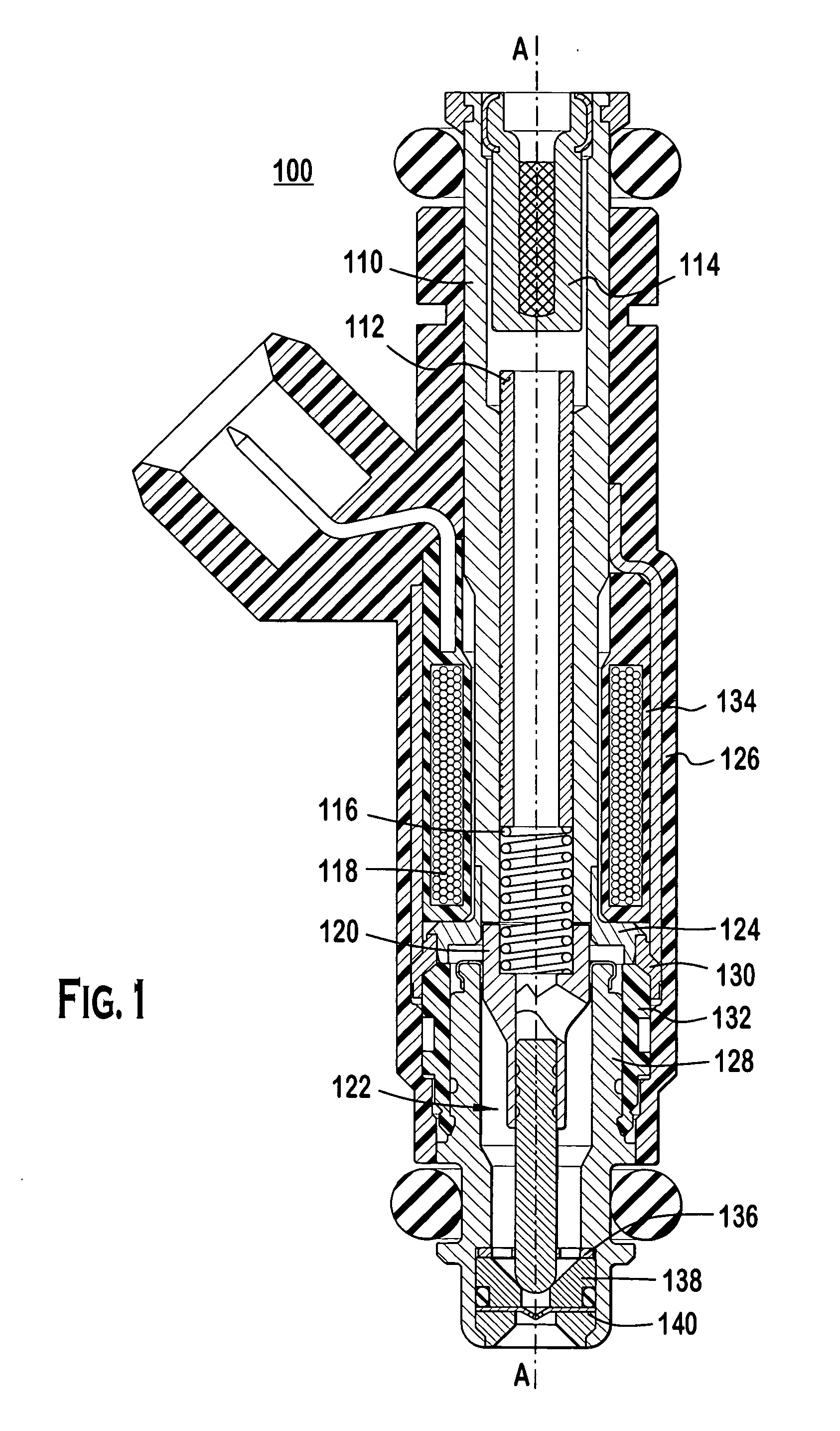
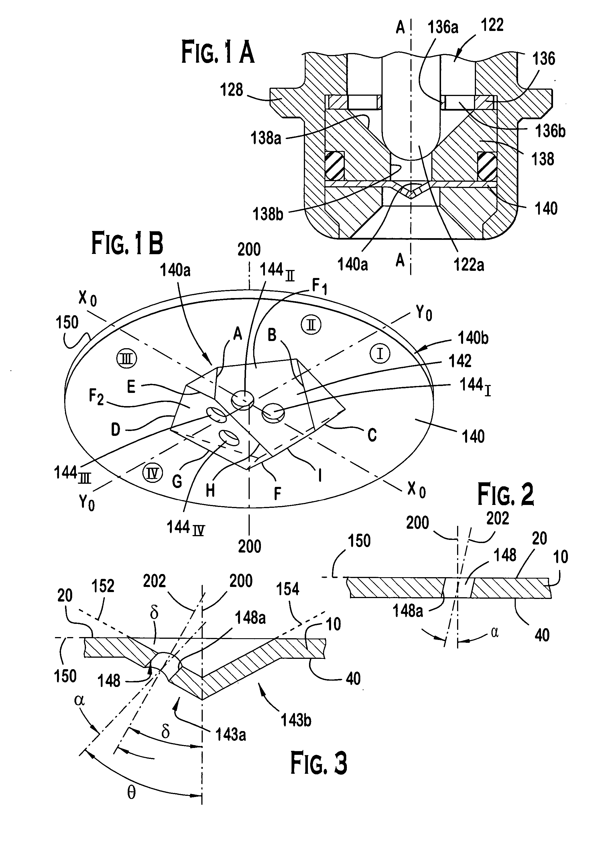
[0025]FIGS. 1-3 and 5-11 illustrate the preferred embodiments. In particular, a fuel injector 100 includes: a fuel inlet tube 110, an adjustment tube 112, a filter assembly 114, a coil assembly 118, a coil spring 116, an armature 120, a closure member assembly 122, a non-magnetic shell 124, a fuel injector overmold 126, a body 128, a body shell 130, a shell overmold 132, a coil overmold 134, a guide member 136 for the closure member assembly 122, a seat 138, and an orifice disc 140. The construction of fuel injector 100 can be of a type similar to those disclosed in commonly assigned U.S. Pat. Nos. 4,854,024; 5,174,505; and 6,520,421, which are incorporated by reference herein in their entireties.

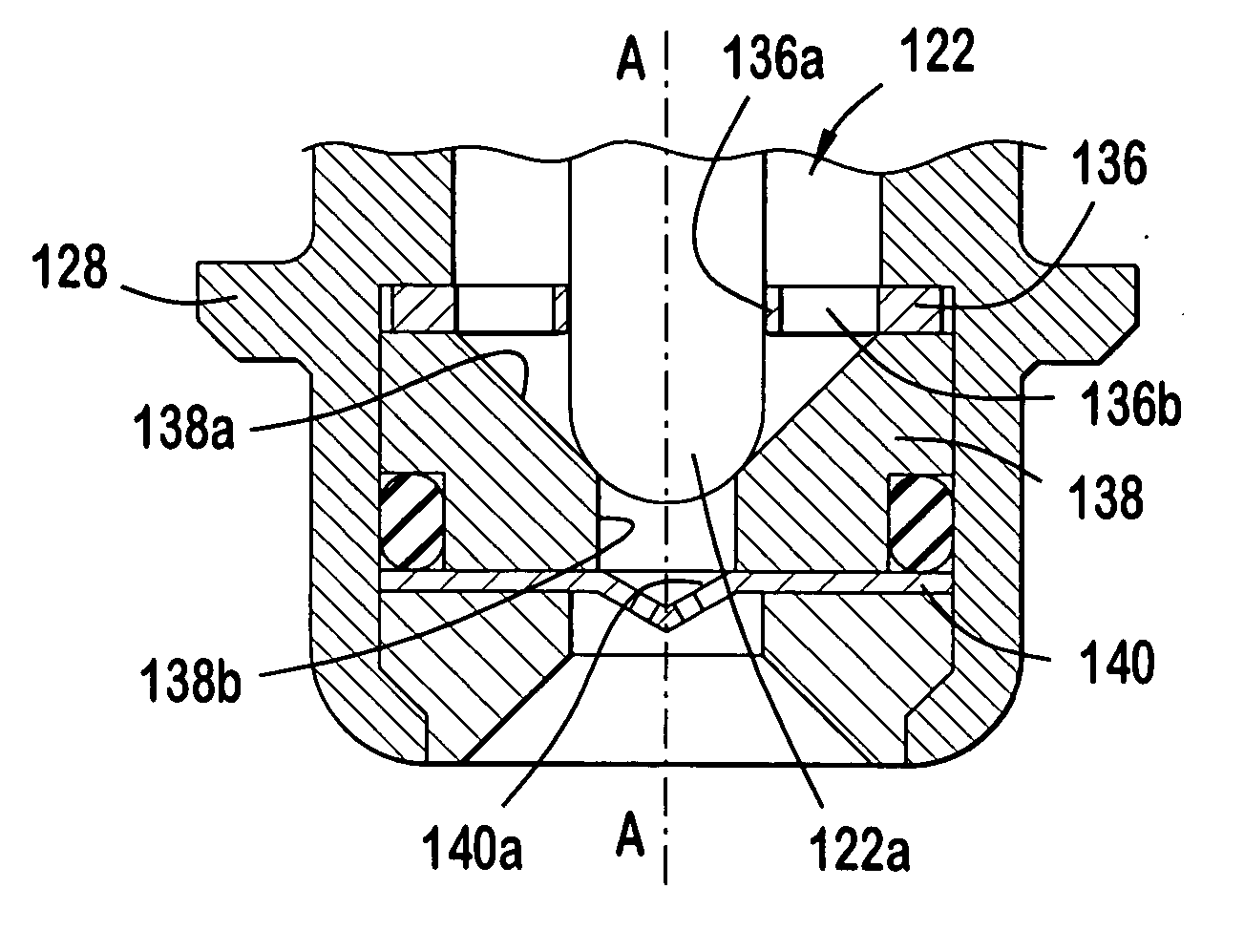
[0026]FIG. 1A shows the outlet end of a body 128 of a solenoid operated fuel injector 100 having an orifice disc 140 according to a preferred embodiment. The outlet end of fuel injector 100 includes a guide member 136 and a seat 138, which are disposed axially interiorly of orifice disc 1...


PUM


Abstract

A fuel injector includes an orifice disc. The orifice disc includes a peripheral portion, a central portion, and an orifice. The peripheral portion is with respect to a longitudinal axis and extends parallel to a base plane. The peripheral portion bounds the central portion. The central portion includes a facet that extends parallel to a plane that is oblique with respect to the base plane. The orifice penetrates the facet and extends along an orifice axis that is oblique with respect to the plane. As such, the orientation of the orifice with respect to the longitudinal axis is defined by a combination of (1) a first relationship of the plane with respect to the base plane, and (2) a second relationship of the orifice axis with respect to the plane. A method of forming a multi-facetted dimple for the orifice disc is also described.

Description

FIELD OF INVENTION [0001] This invention relates generally to electrically operated fuel injectors of the type that inject volatile liquid fuel into an automotive vehicle internal combustion engine, and in particular the invention relates to a novel thin disc orifice member for such a fuel injector. BACKGROUND OF THE INVENTION [0002] It is believed that contemporary fuel injectors must be designed to accommodate a particular engine. The ability to meet stringent tailpipe emission standards for mass-produced automotive vehicles is at least in part attributable to the ability to assure consistency in both shaping and aiming the injection spray or stream, e.g., toward intake valve(s) or into a combustion cylinder. Wall wetting should be avoided. [0003] Because of the large number of different engine models that use multi-point fuel injectors, a large number of unique injectors are needed to provide the desired shaping and aiming of the injection spray or stream for each cylinder of an ...

Claims


Application Information

Patent Timeline
Patent Type & Authority Applications(United States)
IPC IPC(8): F02M51/06F02M61/18
CPCF02M61/1853F02M51/06
Inventor JOSEPH, J. MICHAEL
Owner VITESCO TECH USA LLC
Why Eureka
Try Eureka