Programmable Zoned End Effector

Active Publication Date: 2010-02-18
AMF AUTOMATION TECH
View PDF17 Cites 90 Cited by
  • Summary
  • Abstract
  • Description
  • Claims
  • Application Information

AI Technical Summary

Benefits of technology

[0009]Briefly described, one form of the present process concerns a method of selectively robotically collecting work products in a selected pattern from an accumulation of work products and placing the work products in a receptacle. The method includes orienting an end effector to engage some of the work products in the accumulation of work products with a plurality of vacuum retrievers in a first zone of the vacuum retrievers, applying a sub-atmospheric air pressure to the vacuum retrievers in the first zone of vacuum retrievers while avoiding drawing an air pressure in the remaining vacuum retrievers, and retrieving work products from the accumulation of work products with the vacuum retrievers in the first zone of the end effector. Then re-orienting the end effector with respect to the accumulation of work products and re-engaging the accumulation of work products with a second zone of the vacuum retrievers. Sub-atmospheric air pressure is applied to the vacuum retrievers in both the first and second zones of vacuum retrievers, and the work products are retrieved with the vacuum retrievers in the second zone of the end effector. These steps may be repeated for several picks until the desired pattern of work products are gathered on the end effector. Then the end effector places the work products in registration with a receptacle, and the sub-atmospheric air pressure to the work products is terminated to release the work products from the end effector.

Problems solved by technology

The system described above is not ideal when several different zones are required to conduct the picking functions and / or the zones must change in shape for picking different products.
If there are too many pick zones of vacuum retrievers then the vacuum lines become small and restrict the vacuum flow.
This is cost prohibitive as some producers have dozens of different shaped and sized products and would require dozens of different end effectors.
This may be a solution to some of the problems but is limited because it is not zoned and therefore cannot perform multiple picks.
If multiple picks are attempted then the first pick often fails due to leakage from the other open cups.

Method used


Image

  • Programmable Zoned End Effector
  • Programmable Zoned End Effector
  • Programmable Zoned End Effector

Examples


Embodiment Construction

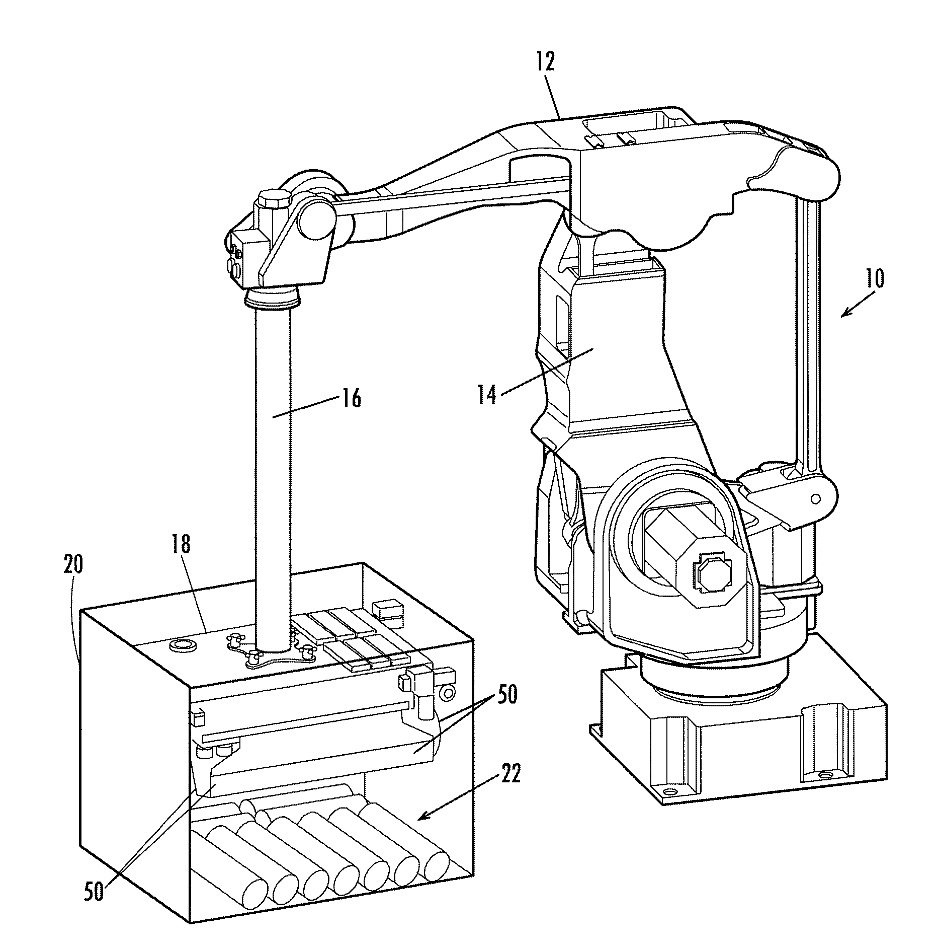
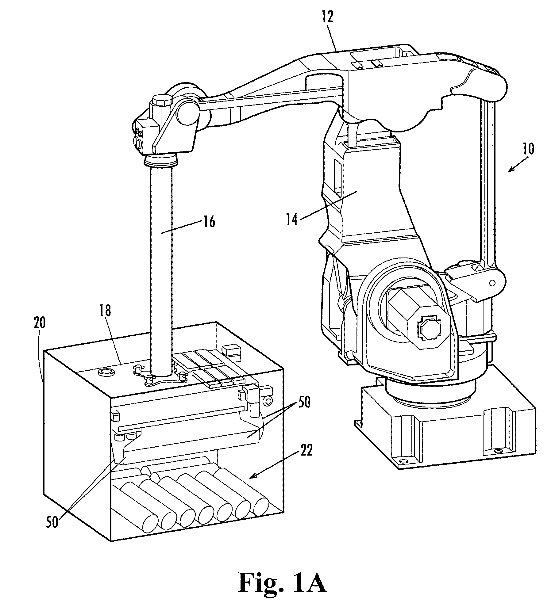
[0022]Referring now in more detail to the drawings, in which like numerals indicate like parts throughout the several views, FIG. 1A illustrates a robot 10 of conventional articulating design, being pivotal about and upright axis, having a rocker arm 12 mounted on a rotary stanchion 14, and control arm 16 that has the capacity to rotate in the distal end of the rocker arm 12. The end effector 18 is mounted to the distal end of the control arm 16 and its movements are controlled by a program entered in the robot's computer system. The end effector can be rotated, raised, lowered and moved in lateral directions, as is common in the art and in accordance with its programmable control system.

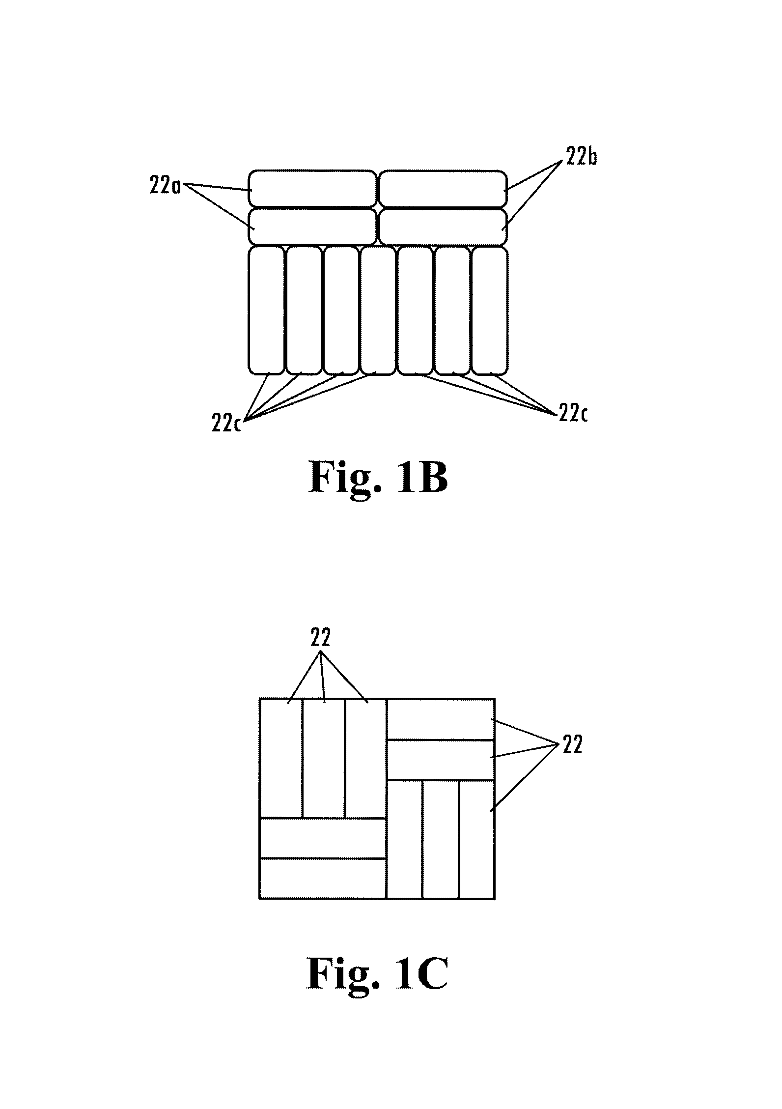
[0023]As shown in FIG. 1A, the end effector 18 has been placed in alignment with the receptacle 20 which is a packing container. The work products 22 have been released by the end effector 18 and have been deposited on the bottom wall of the receptacle 20. In the embodiment illustrated, the receptac...


PUM


Abstract

An end effector for a robot having an array of suction cups includes an air control valve connected to each suction cup. Each valve can be individually operated so that specific zones of suction cups may be activated while others are dormant. The dormant suction cups are closed to the sub-atmospheric pressure, so that leakage of air through unused suction cups is avoided, while only the suction cups of the selected zone perform the picking of the work products. This allows the end effector to provide accurate and constant sub-atmospheric pressure to the work products during the picking process.

Description

TECHNICAL FIELD[0001]The present disclosure concerns packaging equipment and, more particularly, concerns a robotic packaging apparatus that includes an end effector for collecting work products of different shapes and sizes in different patterns for delivery to a receptacle, such as to a shipping container.BACKGROUND OF THE DISCLOSURE[0002]In robotic packaging operations, a producer might desire to ship work products in shipping containers of a standard shape and size. The shape and size of the individual work products might be different from one job to the next. In order to ship in standard size containers it may be required to retrieve and collect the products of one size and shape on the end effector of the robot in a different pattern than for other products.[0003]For example, in the bakery industry a producer typically will produce several sizes of loaves of bread from time to time and has one basket size in which he / she ships the products. The different products may fit best ...

Claims


Application Information

Patent Timeline
IPC IPC(8): B25J15/06
CPCB25J15/0052B25J15/0616B66C1/0256B66C1/0243B65G47/91
Inventor PARNELL, GEOFFREY JAMES
Owner AMF AUTOMATION TECH
Why Eureka
Try Eureka