Vehicle vacuum system

a vacuum cleaner and vehicle technology, applied in the field of automobile accessories, can solve the problems of difficult to create a space-efficient, simple operation, mechanically reliable device, and limited ability to reach all areas of the passenger vehicl

Inactive Publication Date: 2010-02-25
JOHNSON CLINT +1
View PDF16 Cites 14 Cited by
  • Summary
  • Abstract
  • Description
  • Claims
  • Application Information

AI Technical Summary

Problems solved by technology

Since automobiles (e.g., all types of cars, trucks and other vehicles) vary greatly is size, design specification, power, interior features, frame, trunk space and passenger space, it is a problem to design a vacuum system which is optimized for all vehicles.
It is particularly difficult to create a space-efficient, simply operated, mechanically reliable device without making any design modifications to the dashboard, trunk components, carpeting frame or other components of the automobile.
However, the prior art has generally taught against making modifications to vehicle body components themselves and / or have required building of special compartments.
Further, these designs have required complex retractable hosing, and have had limited ability to reach all areas of a passenger vehicle.
They are expensive to manufacture both before-market and after-market.
Many prior art attempts to develop a vehicle vacuum system have relied on complex and limiting configurations involving storage of a canister in a console portion between automobile seats, space-inefficient trunk components and expensive retractable hoses prone to malfunction,
This design is not effective for picking up debris such as fast food wrappers.
The concealed and retractable hose taught by the '528 application is prone-to malfunctioning, as well as is costly.
The canister is not designed or adapted for mounting in the trunks of vehicles having variable dimensions.
The canister is also not contoured to be space efficient.
The canister of the '468 application is of limited power, and utilizes a “direct port” without transitory tubing that allows debris to be vacuumed and transported to a canister from within various locations of the vehicle.
The range of access to the passenger compartment for cleaning is limited by the location of the canister and length of the hose, which poses a serious limitation.
In addition, the vacuum system takes up space in the passenger compartment, it is also an after-market device, and it does not utilize trunk space, the space between the under-body of the vehicle, or battery power.
Systems in the prior art have been ineffective because the devices take up passenger compartment space and are limited in power and cleaning range.
Additionally, vehicles vary greatly in size and style therefore one system is not compatible with all types of vehicles.
Furthermore, such designs lack desired child-safety features.

Method used


Image

  • Vehicle vacuum system
  • Vehicle vacuum system
  • Vehicle vacuum system

Examples


Embodiment Construction

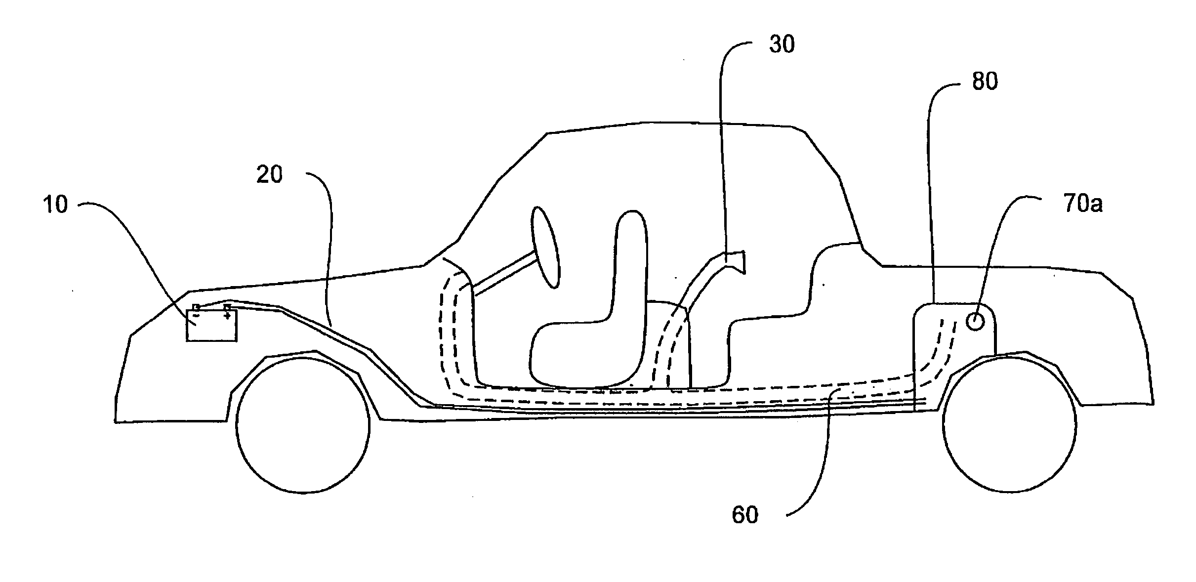
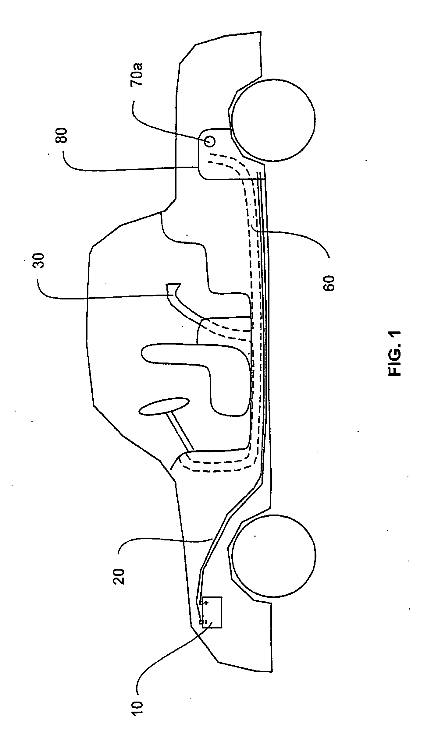
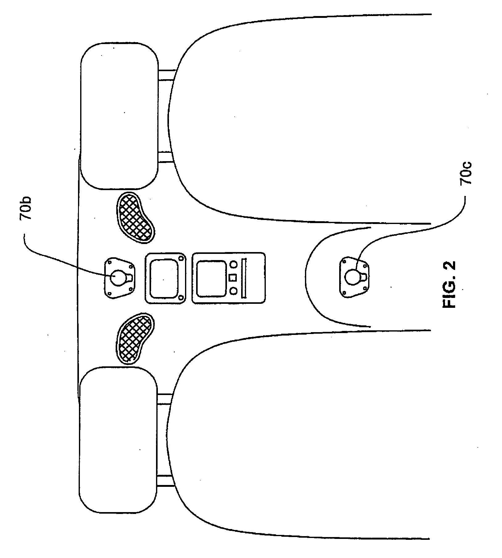
[0027]For the purpose of promoting an understanding of the present invention references are made in the text hereof to embodiments of a central vacuum cleaner system for a vehicle, only some of which are depicted in the figures. It should nevertheless be understood that no limitations on the scope of the invention are thereby intended. One of ordinary skill in the art will readily appreciate that modifications such as the dimensions, size, and shape of the components, alternate but functionally similar locations, and the inclusion of additional elements are deemed readily apparent and obvious to one of ordinary skill in the art, and all equivalent relationships to those illustrated in the drawings and described in the written description do not depart from the spirit and scope of the present invention. Some of these possible modifications are mentioned in the following description. Therefore, specific details disclosed herein are not to be interpreted as limiting, but rather as a re...


PUM


Abstract

A central vacuum cleaner system for an automobile which comprises one or more portals located inside the passenger compartment of an automobile and / or in the space optimized canister located in the trunk or rear of the automobile Transitory tubing connects the one or more portals to the space optimized canister wherein debris is collected and stored. Debris can be placed directly in the portal or a hose and / or additional attachments may be attached to the portal. A portal cover covers the one or more portals blocking the portal when debris is not being placed directly in the portal or when no hose is attached. The central vacuum cleaner system may be powered using the automobile's battery or an external battery.

Description

FIELD OF INVENTION[0001]This invention relates generally to the field of automobile accessories and more specifically to a central vacuum cleaner system to be installed in an automobile at the time of manufacturing.BACKGROUND[0002]There have been many attempts in the prior art to develop an vehicle vacuum system designed to remain in an automobile; however, they have all focused on after-market systems which are purchased by a consumer and installed or used without any structural or design modifications to the automobile components. Since automobiles (e.g., all types of cars, trucks and other vehicles) vary greatly is size, design specification, power, interior features, frame, trunk space and passenger space, it is a problem to design a vacuum system which is optimized for all vehicles. It is particularly difficult to create a space-efficient, simply operated, mechanically reliable device without making any design modifications to the dashboard, trunk components, carpeting frame or...

Claims


Application Information

Patent Timeline
Patent Type & Authority Applications(United States)
IPC IPC(8): B60S1/64
CPCB60S1/64
Inventor JOHNSON, CLINTGAPP, STEVE
Owner JOHNSON CLINT
Why Eureka
Try Eureka