
Low temperature showcase

Active Publication Date: 2010-02-25
SANYO ELECTRIC CO LTD
View PDF2 Cites 24 Cited by
  • Summary
  • Abstract
  • Description
  • Claims
  • Application Information

AI Technical Summary

Benefits of technology

[0016]Therefore, it is possible to suppress a disadvantage that water droplets attached to the upper parts of the doors fly and scatter to a user during the opening / closing operation of the doors or that a floor surface is wetted by the water droplets. Moreover, in this corresponding part, dew condensation water is not easily attached to the surface of the middle pillar, whereby the closely attaching properties to the back surfaces of the doors can be improved, and the leakage of the cold air from the display chamber can be suppressed.
[0019]In consequence, the dew condensation does not easily occur vertically on the surface of the middle pillar duct member which comes in contact with outside air. Therefore, the dew condensation does not easily occur even on the gaskets of the doors which abut on the front surface of the middle pillar duct member, and it is possible to suppress a disadvantage that fingers are wetted during the opening / closing operation of the doors or that the floor surface is wetted by the water droplets attached to the back surfaces of the doors. Moreover, the dew condensation water is not easily attached to the surface of the middle pillar, whereby the closely attaching properties of the front surface of the middle pillar to the gaskets of the doors can be improved, and the leakage of the cold air from the display chamber can be suppressed.

Problems solved by technology

When such dew condensation occurs, a disadvantage is generated that fingers for opening / closing the glass doors 106 are wetted by dew condensation water attached to the middle pillar 105 and the like during the opening / closing of the glass doors 106 or that clothes are wetted by bounding dew condensation water during the opening / closing operation.
Furthermore, there is generated a disadvantage that water droplets attached to the glass doors 106 due to the dew condensation drop down to wet the surface of an installation floor.
Therefore, the power consumption of the showcase itself increases, and the steep rise of running cost is disadvantageously caused.

Method used


Image

  • Low temperature showcase
  • Low temperature showcase
  • Low temperature showcase

Examples


Embodiment Construction

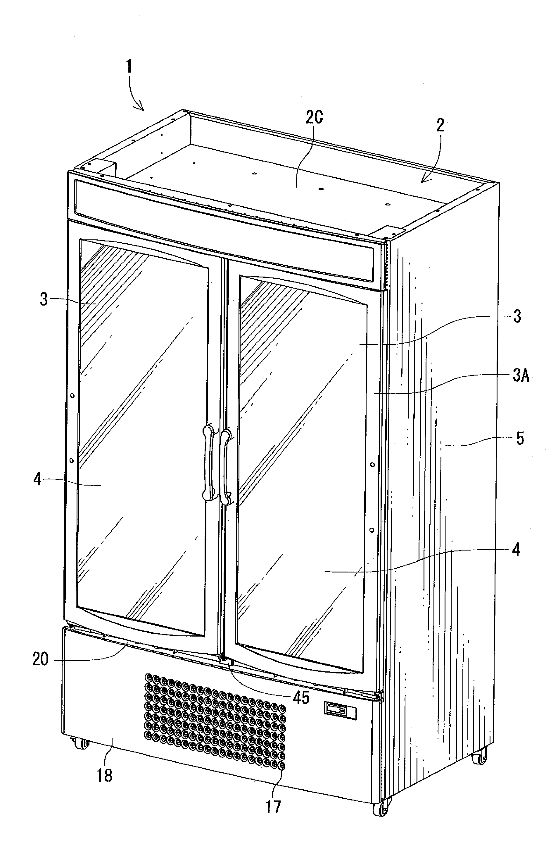
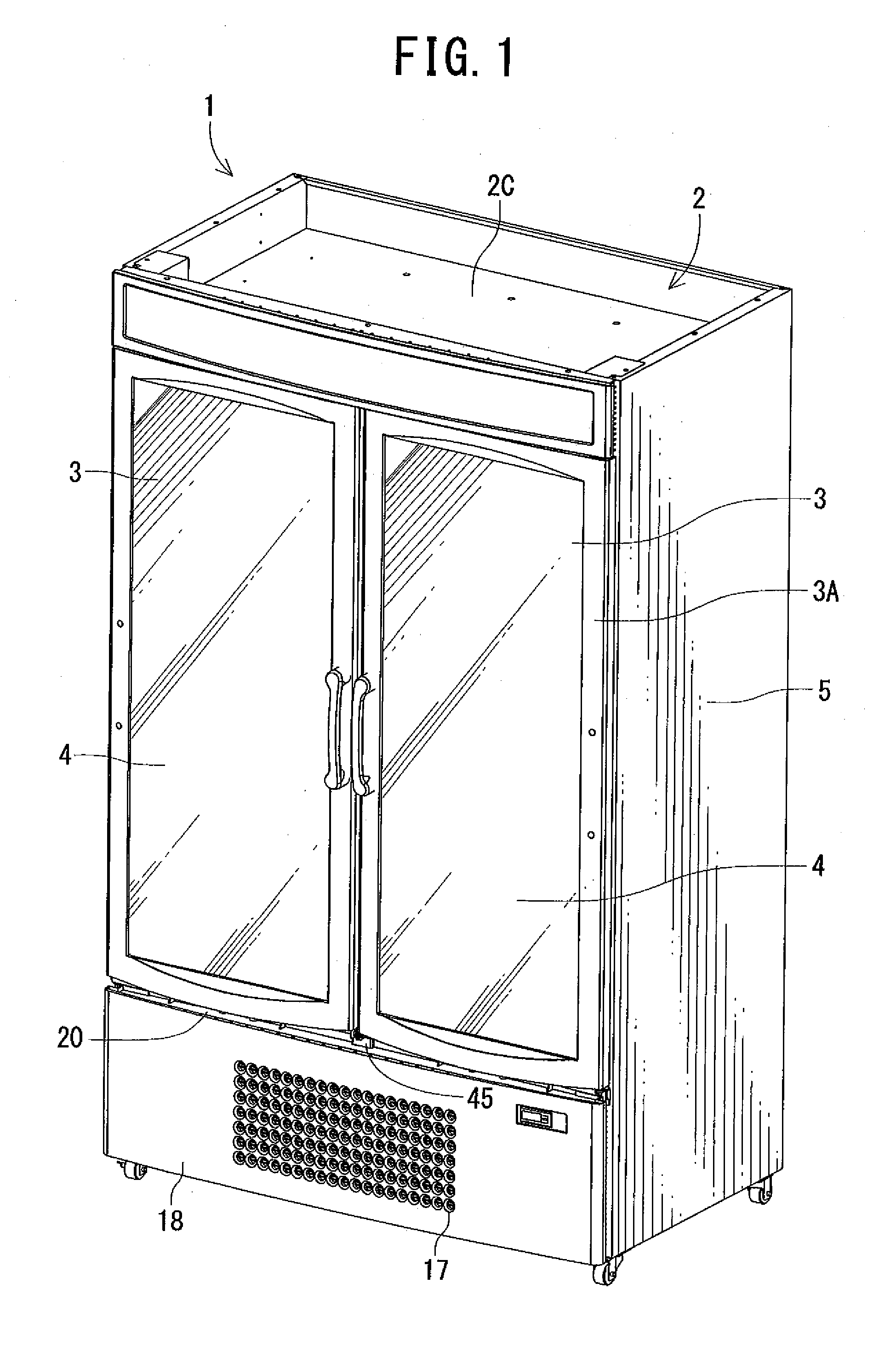
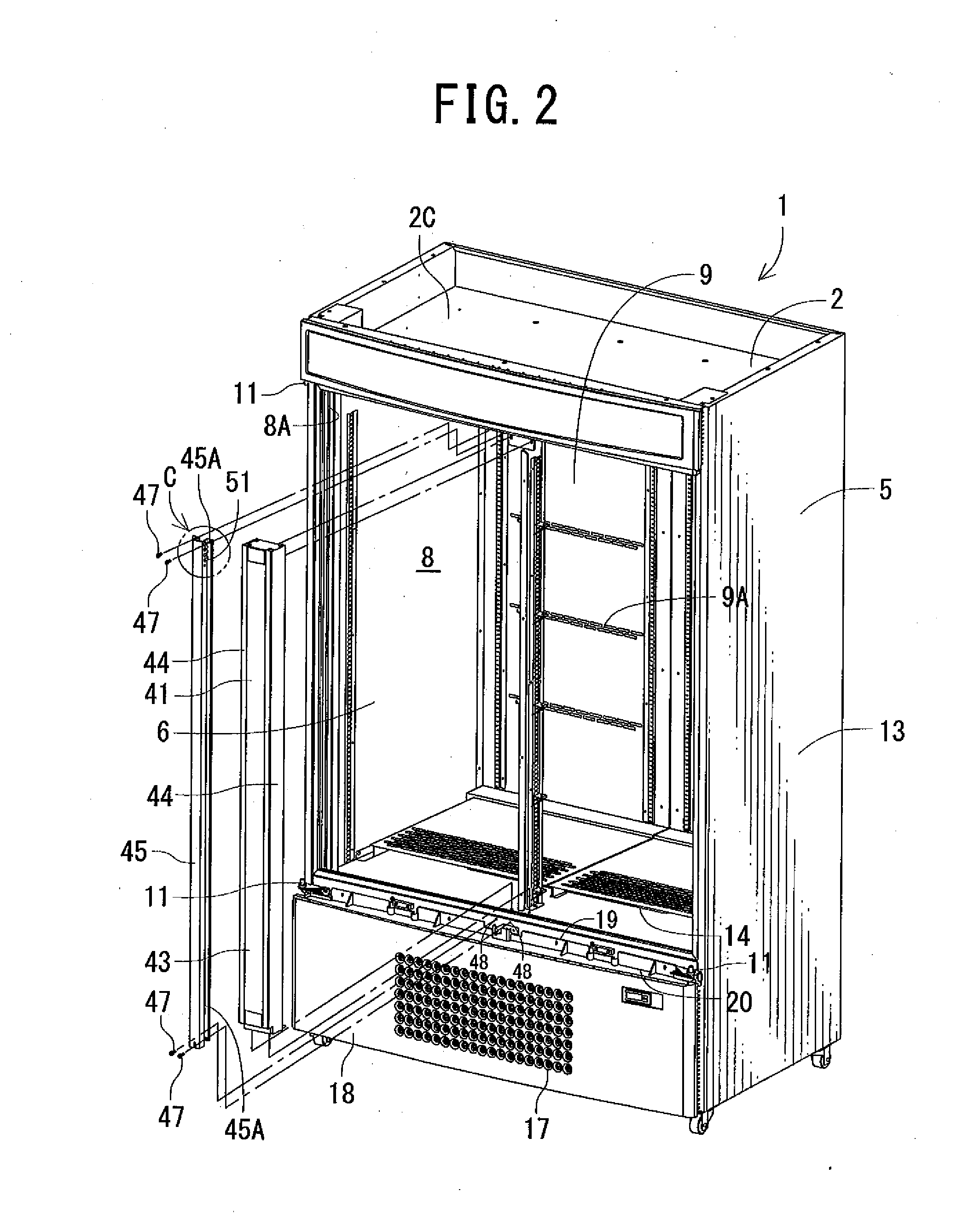
[0032]Next, an embodiment of the present invention will be described with reference to the drawings.

[0033]A showcase 1 of the present embodiment is a low temperature showcase which is installed in a store such as a supermarket or a convenience store and which displays commodities while cooling the commodities, and a main body 2 is made of an insulating box member (an insulating wall) having an opening in the front surface thereof. This main body 2 includes an outer box 5 which opens in the front surface of the main body and which is made of a steel plate; an inner box 6 which is incorporated in the outer box 5 with a space being left from the front surface of the main body and which opens in the front surface of the main body and which is made of a steel plate or a hard synthetic resin; and an insulating material 7 made of foam polyurethane charged between the outer box 5 and the inner box 6 in a foaming state. It is to be noted that in the present embodiment, at the upper edge of t...


PUM


Abstract

An object is to provide a low temperature showcase in which waste heat from a condenser and the like can be utilized by a simple constitution to effectively eliminate dew condensation on a middle pillar, particularly on gasket of upper part of a door. The low temperature showcase includes a middle pillar whose front surface abuts on the gasket of the door; a machine chamber disposed outside a main body under a display chamber and including the condenser, a fan for the condenser and the like, and the showcase further includes a middle pillar duct member which is vertically attached to the middle pillar and in which a middle pillar duct is defined, a leading portion which leads air from the machine chamber into the middle pillar duct, and exhaust holes which discharge the air flowing upwards through the duct to the outside of the gasket between the upper part of the door and the main body.

Description

BACKGROUND OF THE INVENTION[0001]The present invention relates to a low temperature showcase in which an opening in the front surface of a display chamber is openably closed with doors.[0002]A conventional type of low temperature showcase is installed in a store such as a convenience store or a supermarket, and an opening in the front surface of an insulating box member having a display chamber in the showcase is closed with doors (e.g., glass doors) (e.g., see Japanese Patent Application Laid-Open No. 9-101075 (Patent Document 1)). Moreover, a machine chamber is disposed under the insulating box member, and a compressor, a condenser, a fan for the condenser and the like are arranged in this machine chamber so as to form a freezing cycle of a cooling device. Moreover, a cooler similarly forming the freezing cycle is disposed in the display chamber, and the inside of the display chamber is cooled to a predetermined low temperature by this cooler.[0003]Moreover, a middle pillar is pro...

Claims


Application Information

Patent Timeline
IPC IPC(8): A47F3/04F25B1/00
CPCA47F3/0426F25D2323/021F25D21/04
Inventor IGUCHI, HARUNOBUYAMAZAWA, KEISUKEITABASHI, TATSUYA
Owner SANYO ELECTRIC CO LTD
Learn More