Covered in-floor receptacle box

a receptacle box and floor technology, applied in the field of in-floor receptacle boxes, can solve the problems of not revealing the possibility of rearranging the chambers, the cord represents a danger to anyone traversing the floor, and the littrell does not disclose the load-bearing capabilities of the lid

Active Publication Date: 2010-03-04
FSR
View PDF15 Cites 31 Cited by
  • Summary
  • Abstract
  • Description
  • Claims
  • Application Information

AI Technical Summary

Benefits of technology

[0026]In one embodiment of the present invention, the in-floor electrical conduit box lid is designed to meet H20 load ratings, using a ⅞ inch thick alloy-6061-T6 heat-treated aluminum lid with an integrated floor-covering-edge protective flange. Additional structure that improves the load-bearing capabilities of the lid include a conduit-box-attached floor-covering-edge protective rim or flange constructed of ⅛ inch thick stainless steel alloy, designed and fitted to cantilever horizontally out away from the box so as to be supported by the conduit box's surrounding concrete floor structure. This allows transfer of the load of the weight on the lid to be distributed down into the structure of the building itself, which, by necessity, would be designed to easily support any such weights that are allowed, by code, into the building.

Problems solved by technology

However, these cords represent a danger to anyone traversing the floor.
While students sitting in a lecture hall might not be at risk of tripping over these cords and cables, the same cannot be said of wedding attendees who are dancing across a dance floor.
However, Littrell does not disclose that the chambers can be rearranged, or that the chambers can accommodate various types of connections.
However, Arthur et al. does not teach that different types of cables and wires can easily be accommodated.
However, Pudims et al. does not describe an electrical floor box that can, by design, be easily internally rearranged to accommodate different types of temporary or permanent cables or wires.
However, Young et al. does not disclose an electrical floor box that can, by design, be easily internally rearranged to accommodate different types of temporary or permanent cables or wires.
However, Whitehead et al. does not teach an electrical floor box that can, by design, be easily internally rearranged to accommodate different types of temporary or permanent cables or wires.

Method used


Image

  • Covered in-floor receptacle box
  • Covered in-floor receptacle box
  • Covered in-floor receptacle box

Examples


Embodiment Construction

[0042]The following description of preferred embodiments is presented to describe the present invention and is not to be construed to limit the scope of the appended claims in any manner whatsoever.

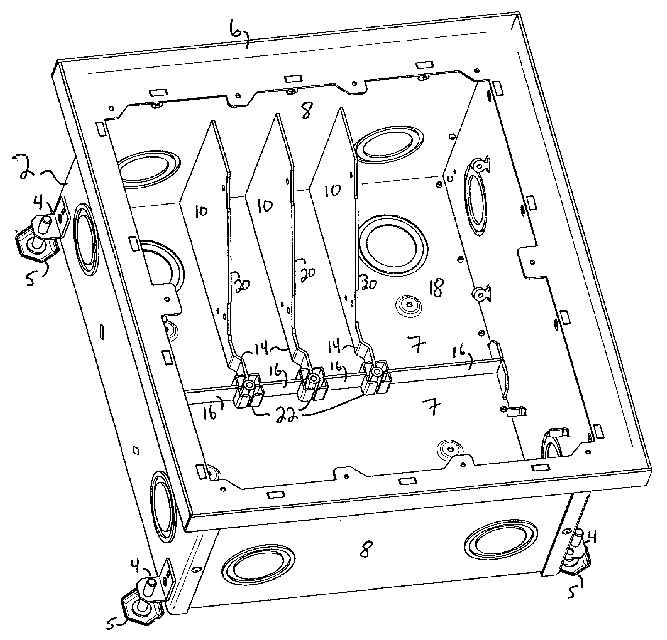
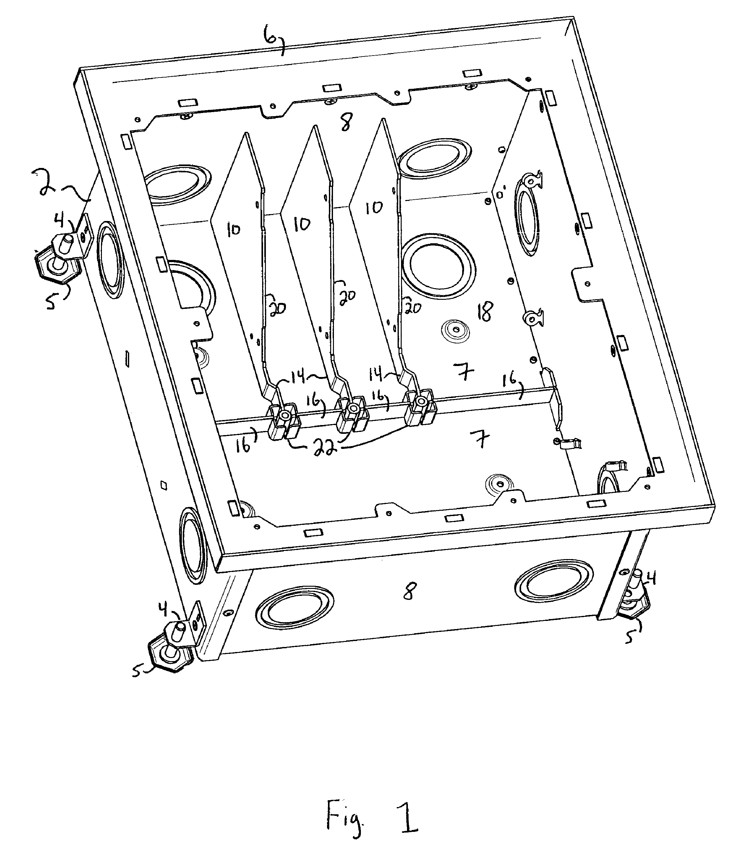
[0043]As best shown in FIG. 1, the user configurable in-floor receptacle or electrical conduit box (2) preferably has a plurality of supporting legs (4) that can be fixed or adjustable, to assist fitting the box to the required height of the in-floor opening. In a preferred embodiment, each leg (4) is provided with a screw-adjustable foot (5) which can be turned to raise or lower the in-floor electrical conduit box (2) relative to the surface of the floor in which the box is to be installed.

[0044]Less preferred, although encompassed by the present invention, is an in-floor electrical conduit box (2) with fixed feet, with other types of adjustable feet, or without any feet at all.

[0045]The in-floor electrical conduit box (2) preferably includes a lip (6) upon which a lid (36, FIG. 4) is pl...


PUM


Abstract

An in-floor receptacle or electrical conduit box with a compartment divider removably attached to a gang-plate divider, a gang-plate divider removably attached to a gang-unit holder, at least one gang-unit holder removably attached to the inside of the box, and at least one knockout located on each side or floor of the box. The in-floor electrical conduit box enables the connection of permanent cables, wires or cords to temporary cables, wires or cords.
The in-floor electrical conduit box further comprises a lid with at least one removable door whereby the removal of the door permits cable access to the box while the box is still covered.

Description

FIELD OF THE INVENTION[0001]The present invention relates to an in-floor receptacle box. More particularly, the present invention relates to an in-floor receptacle box that is adaptable to different user-configurable gang-unit arrangements. Even more particularly, the present invention relates to an in-floor receptacle box that can be used while being covered by a weight-bearing lid.BACKGROUND OF THE INVENTION[0002]Many venues, such as educational and entertainment halls, use advanced audio and video (“AV”) equipment during routine functions and business. For example, a banquet hall may have a complete sound system to which it allows visiting musical bands or DJs to connect microphones, stereo systems or other equipment. A college lecture hall may have a full video system, to which it allows professors to connect laptop computers, DVD players or other equipment. Likewise, a community center or exhibition hall may have a full video or sound system, to which traveling shows may connec...

Claims


Application Information

Patent Timeline
Patent Type & Authority Applications(United States)
IPC IPC(8): H01R13/46H05K5/06
CPCH02G3/185
Inventor HANSEN, DAVIDMACALUSO, JOHN
Owner FSR
Why Eureka
Try Eureka