Force level control for an energy absorber for aircraft

Inactive Publication Date: 2010-03-04
AIRBUS OPERATIONS GMBH
View PDF24 Cites 4 Cited by
  • Summary
  • Abstract
  • Description
  • Claims
  • Application Information

AI Technical Summary

Problems solved by technology

In the case of fixed attachment elements it is often disadvantageous, in particular in the even of intense accelerations, such as those that can occur in the event of severe turbulence or for example, also with an emergency landing, that the resulting acceleration forces are transmitted directly from the primary structure of the aircraft over the holder to the attached inboard device.
A breakdown of the holder, such as for example, by breaking or bursting out from the inboard device based on excessive acceleration forces may occur, which may lead to damage to the holder, the inboard device, or the primary structure of the aircraft and further, may endanger or injure the passenger

Method used


Image

  • Force level control for an energy absorber for aircraft
  • Force level control for an energy absorber for aircraft
  • Force level control for an energy absorber for aircraft

Examples


Example

[0070]In the following description of the figures, the same reference numerals are used for the same or similar elements.

[0071]The representations in the figures are schematic and not to scale.

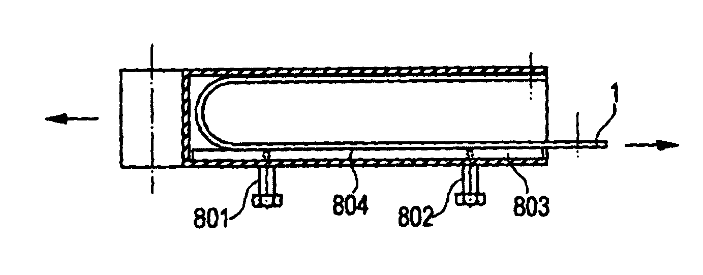
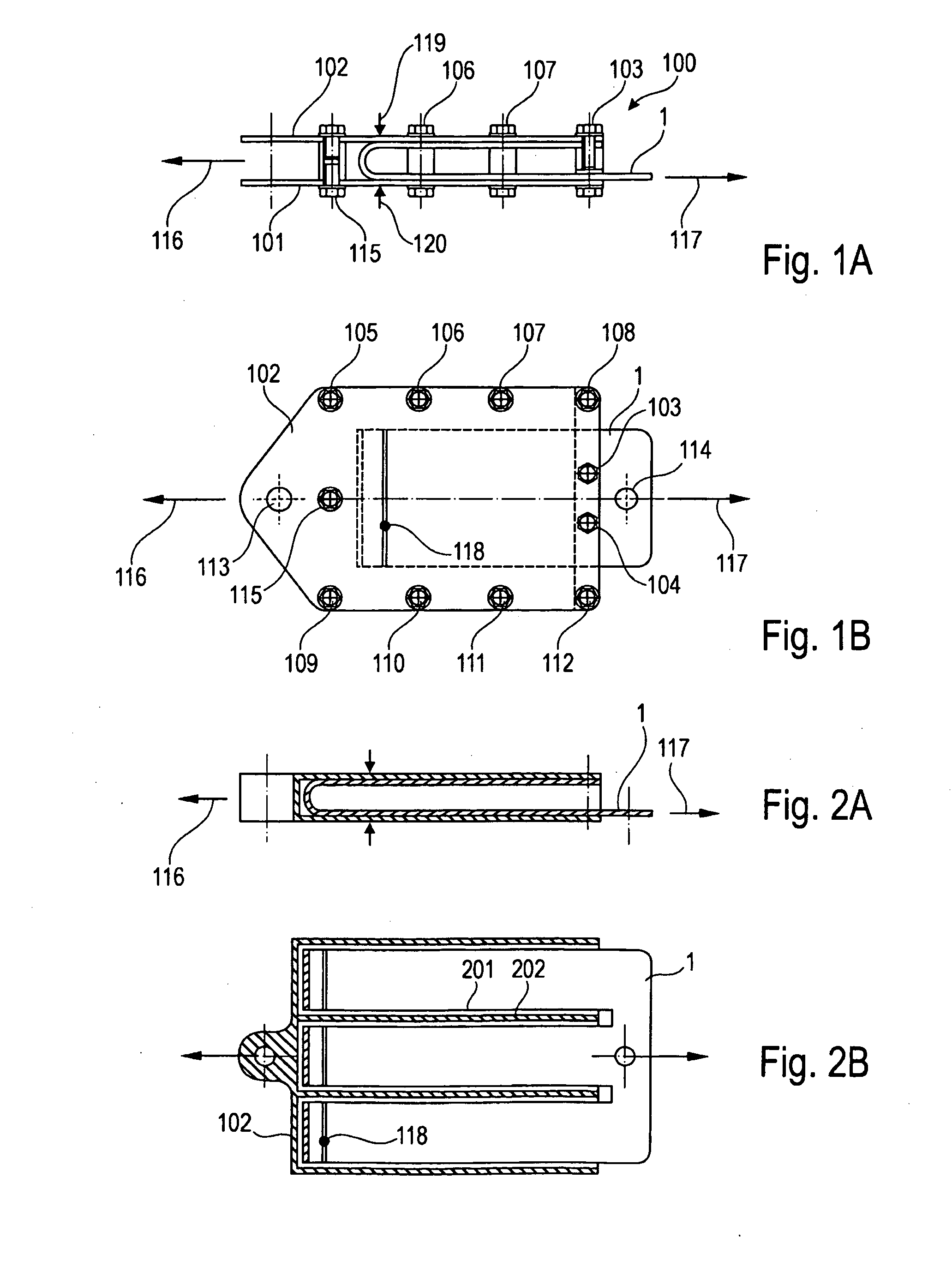
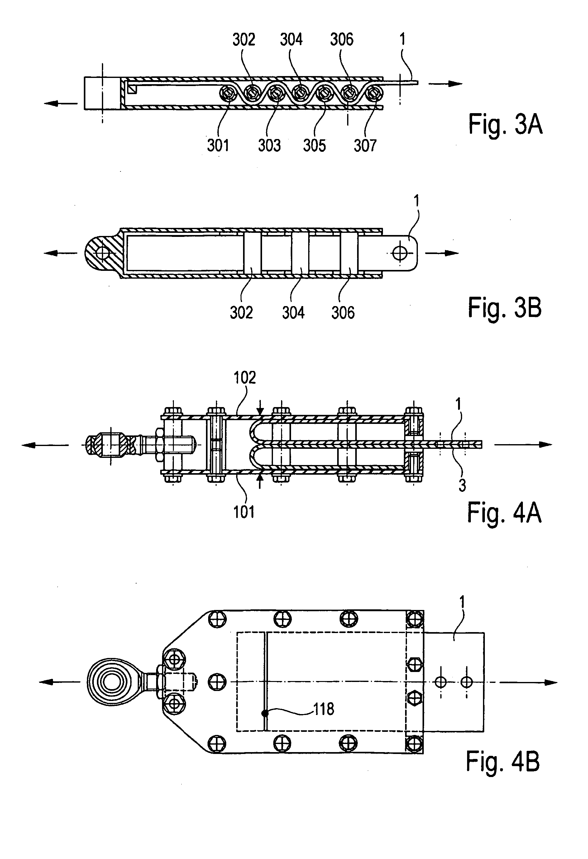
[0072]FIG. 1A shows a schematic cross-sectional representation of an energy absorber according to an exemplary embodiment of the present invention. The energy absorber 100 has a lower housing region 101 and an upper housing region 102, between which the energy absorber element is mounted.

[0073]The energy absorber 100, in which this energy absorber elements 1 are installed, is subdivided basically into so-called single deckers with a plate or sheet or with multiple plates or sheets placed in one another and so-called multiple decker with two or more sheets running opposite to one another (which can comprises respectively again multiple sheets placed in one another).

[0074]Thus, multiple sheets may be nested in one another, in order to achieve for example an optimization of the cover layer load, ...


PUM


Abstract

A force level control for an energy absorber is provided for aircraft, and includes an adjustment element and a housing, whereby via the adjustment element, a bending radius of the energy absorber element is continuously adjustable in the housing.

Description

This application claims the benefit of German Patent Application No. 10 2006 007 028.3 filed Feb. 15, 2006, and of U.S. Provisional Application No. 60173,760. filed Feb. 15, 2006, the disclosures of which are hereby incorporated herein by reference.FIELD OF THE INVENTION[0001]The present invention relates to energy absorbers for aircraft. In particular, the present invention relates to a force level control for an energy absorber for an aircraft and the use of such a force level control energy absorber in an aircraft.TECHNOLOGICAL BACKGROUND OF THE INVENTION[0002]In aircraft, holders or attachment elements for holding and attaching inboard devices, such as ceiling liners, overhead bins, or monuments, are used. In the case of fixed attachment elements it is often disadvantageous, in particular in the even of intense accelerations, such as those that can occur in the event of severe turbulence or for example, also with an emergency landing, that the resulting acceleration forces are...

Claims


Application Information

Patent Timeline
IPC IPC(8): F16F7/12
CPCB60R22/28B64C1/062F16F7/128F16F7/123B64D25/04
Inventor HUMFELDT, DIRKHARRIEHAUSEN, MICHAELSCHRODER, JANSPERBER, MARTINDEMARY, MICHAEL
Owner AIRBUS OPERATIONS GMBH
Why Eureka
Try Eureka